
Related Manuals for Bacharach MGS-408


Summary of Contents for Bacharach MGS-408
- Page 1 Gas Detection Controller for Commercial & Industrial Applications Fixed Gas Detection User Manual P/N: 1100-2295 | February 2020 Revision 1...
- Page 2 Bacharach, Inc. warrants to buyer that it will convey good title to this product. Bacharach’s liability and buyer’s remedy under this warranty of title are limited to the removal of any title defects or, at the election of Bacharach, to the replacement of this product or parts thereof that are defective in title.
-
Page 3: Table Of Contents
Mounting the Gas Detection Controller ..............10 3.5. Electrical Wiring ......................11 3.6. Communications Connections ................. 12 3.6.1 MGS-408 Gas Detection Controller Network ..................12 3.6.2 Integration with Building Management System ................13 3.7. Connecting External Alarms ..................14 3.7.1 Overview ............................... - Page 4 MGS-408 User Manual 4.2.5 LCD Contrast ............................19 4.2.6 LED Brightness & Auto-dimming ....................... 19 4.2.7 Date/Time ............................. 20 4.2.8 Password Protection ........................... 20 4.2.9 Factory Reset............................21 4.2.10 Update Firmware ..........................21 4.3. Channel Summary and Setup ................... 22 4.3.1...
- Page 5 MGS-408 User Manual Additional Information ....... 41 7.1. Disposing of Instrument ................... 41 7.2. Technical Specifications .................... 41 Parts and Accessories ........42 8.1. Part Numbers ......................42 8.2. Service Center Locations ................... 43 1100-2295 Rev 1...
-
Page 6: Introduction
1. Introduction 1.1. About this Manual Thank you for investing in a Bacharach MGS-408 Gas Detector Controller. To ensure operator safety and the proper use of the controller, please read the contents of this manual for important information on the operation and maintenance of the instrument. -
Page 7: Iconography
WARNING: Always remove AC power before working inside the MGS-408 enclosure and exercise extreme care when accessing the products interior. Only qualified electrical maintenance personnel should perform connections and adjustments. - Page 8 In the case of such occurrence, de-energize the power supply and contact a qualified repair technician or the nearest Bacharach Service Center. CAUTION: Use ONLY the provided cable glands for electrical and communication wiring.
-
Page 9: Product Description
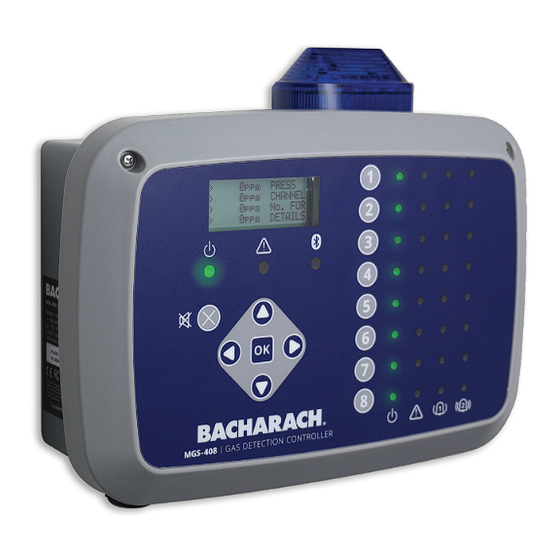
The MGS-408 displays status via an LCD screen and a bank of LEDs that represent the channel / sensor connected to it. Each channel / sensor has a row of dedicated LEDs to indicate the status of the sensor: •... -
Page 10: Intended Use
2.2. Intended Use The MGS-408 provides audio-visual alerts and information pertaining to the status of a centralized gas detector network. This information allows concise, at-a-glance notification of any alarm or fault status regarding a connected gas detector located outside the monitored space, as required by many regulatory codes and standards. -
Page 11: Design Features
MGS-408 User Manual 2.3. Design Features Power Options 100 - 240 VAC, 50/60 Hz, 80 W (max.) Provides power for 1 - 8 compatible Bacharach gas detectors Output/ RS485 Modbus RTU Master for Gas Detectors Communications Diagnostic / Status LEDs... -
Page 12: Components
FAT 32, with a maximum capacity of DOWNLOAD INSTRUCTIONS: For more detailed product information and an installation guide, scan here or visit www.mybacharach.com to access the MGS-408 User Manual (P/N: 1100-2295) and Quick Start Guide (P/N: 1100-2292). Component Description Component Description... -
Page 13: Communication Features
MGS-400 App. 2.5. Communication Features The MGS-408 Gas Detection Controller features full two-way communications via an RS-485 interface. MODBUS RTU is the communication protocol standard. The controller can be configured as a modbus master and be the centralized location for all eight gas sensors or be the modbus slave and connect to a building management system for a complete gas detection solution. -
Page 14: Installation
3.2. Preliminary Inspection The MGS-408 Gas Detection Controller has been thoroughly inspected and tested prior to shipment from the factory. Nevertheless, it is recommended that the instrument be re-checked prior to installation. Inspect the outside of the enclosure to make sure there are no obvious signs of shipping damage. -
Page 15: Suitable / Appropriate Locations
MGS-408 User Manual 3.3. Suitable / Appropriate Locations The MGS-408 Gas Detection Controller should be centrally located in the facility (preferably outside of the mechanical room) and should be easily accessible for visual monitoring and servicing. This is the “split architecture design” for safety of the operator. -
Page 16: Electrical Wiring
AC power neutral (white / blue), live (black / brown) and ground wires to the appropriate terminals, using a screwdriver on the press-to-release tabs. Figure 4-2 - MGS-408 Wiring Diagram Description 24 V DC Out Connector to 24V DC... -
Page 17: Communications Connections
MGS-408 as the power source for the Bacharach gas sensors due to voltage drops in the cable. When using the MGS-408 as a power source for the Bacharach sensors the following needs to be taken into consideration; the total power requirements of the sensors, the wire gauge of the cable being used and the distance to the furthest gas detector. -
Page 18: Integration With Building Management System
(Belden 3106A or equivalent). Use any of the remaining service cable glands to gain access to the interior of the MGS-408 Gas Detection Controller. Locate the Modbus/RS- 485 connector. Secure the wire leads to the connector in the orientation as displayed on the board. -
Page 19: Connecting External Alarms
NOTE: Power for the external alarms can be tapped off the AC IN connector. NOTE: The relay contacts are rated 5A at 250VAC (N.O. contact) and 2A at 250VAC (N.C. contact). (Refer to “Figure 4-1 - MGS-408 Wiring Diagram” on page 16.) -
Page 20: Operation
4.1. Overview 4.1.1 Main Function Every five seconds the MGS-408 Gas Detection Controller collects gas concentration and status information from each connected gas detector. Gas concentration appears on the LCD display and connection status, fault and alarm conditions are indicated by the LED matrix for each channel. -
Page 21: Controller Setup
When all character selections for the screen are completed, press OK to accept the entries. Figure 4-4 - Example of Data Entry Required 4.2. Controller Setup Figure 4-5 - MGS-408 Wiring Diagram Description 24 V DC Out Connector to 24V DC... -
Page 22: Setup Parameters
MGS-408 User Manual 4.2.1 Setup Parameters Before using the controller, various parameters must be set by the user based on how the controller has been wired. Main Menu CONTRLR CONFIG press OK, to access the setup parameters menu. -
Page 23: Audible/Visual (Av) Alarm Beacon
MGS-408 User Manual Figure 4-8 - Toggling the Alarm Setting 4.2.3 Audible / Visual (AV) Alarm Beacon The beacon, if installed, and the internal buzzer may be enabled to indicate an alarm condition. When enabled, the beacon will be energized, and the buzzer will beep, if either a low or high alarm condition exists. -
Page 24: Lcd Contrast
MGS-408 User Manual 4.2.5 LCD Contrast From the LCD contrast setting screen, the contrast can be adjusted from 1-63, with 30 being the default. Main Menu CONTRLR CONFIG LCD CONTRAST press OK , to access the contrast menu. -
Page 25: Date/Time
Figure 4-13 - Date/time Menu 4.2.8 Password Protection The MGS-408 Gas Detection Controller can be password protected to prevent the unauthorized editing of setup parameters. When password protection is enabled, an operator may still navigate between screens to observe settings or monitor network status. -
Page 26: Factory Reset
MGS-408 User Manual Figure 4-14 - Password Protection IMPORTANT: Make note of your password and save it. 4.2.9 Factory Reset Selecting FACTORY RESET will revert all user settings to their factory, out of box, defaults. A confirmation screen will ask the user to confirm their intent since user settings will be lost and you will need to re-configure each channel. -
Page 27: Channel Summary And Setup
MGS-408 User Manual This process may take several minutes. Main Menu CONTRLR CONFIG UPDATE FIRMWARE press OK, to perform a firmware update. Press press OK to proceed; X to exit. Figure 4-16 - Firmware Screen Figure 4-17 - Firmware Reset 4.3. -
Page 28: Channel Setup Overview
MGS-408 User Manual 4.3.1 Channel Setup Overview Prior to setting channel parameters, the installer should verify and record the instrument type, node address and baud rate for each connected detector. All detectors must be set for the same baud rate, either 9600 (default) or 19200, and must have a unique node address. -
Page 29: X) Typ (Instrument Type)
MGS-408 User Manual Press CH (X) (twice) MON (ON/OFF) press OK, to turn monitoring for a channel on or off. Press the arrow keys to select entry, press OK. 4.3.3 CH(X) TYP (Instrument Type) The instrument type parameter indicates what instrument model is connected to CH(X). -
Page 30: Data Logging
SD card can hold up to 10 years of log data. 4.4.2 SD Card Requirements The MGS-408 comes with a 32 GB SD card installed, which can hold up to 10 years worth of log data. A compatible SD card will have 32 GB or less capacity and be formatted in the FAT32 format. - Page 31 MGS-408 User Manual 4.4.3.2 LOGGING(ON/OFF) Enable or disable data logging by setting this item to ON or OFF. To enable/disable data logging: Press the arrow keys to select entry, press OK. 4.4.3.3 SD %FREE Shows the percentage of space remaining on the installed SD card.
-
Page 32: Modbus
BMS communication. Communication parameters may be set from the MODBUS CONFIG menu. The MGS-408 controller acts as a MODBUS master device on the detector side, and as a MODBUS slave device on the BMS side. Main Menu MODBUS CONFIG press OK to access the MODBUS CONFIG... -
Page 33: Slave Baud Rate
MGS-408 User Manual 5.1.3 SLAVE BAUD RATE The MGS-408 controller will us this baud rate to communicate with the upstream BMS or MODBUS master device, either 9600 (default) or 19200. Main Menu MODBUS CONFIG SLAVE BAUD press OK, to change the Slave BAUD: ... -
Page 34: Modbus Registers
MGS-408 User Manual 5.2. MODBUS Registers Register Func Code 04 Item Group Notes Address (read input registers) 0=NOT MONITORED 30001 Sensor 1 is monitored flag Sensor 1 1=MONITORED 1=COM NORMAL, 30002 Sensor 1 communication status Sensor 1 2=COM FAIL Exception code from... - Page 35 MGS-408 User Manual Register Func Code 04 Item Group Notes Address (read input registers) Power of 10 used on concentration, divide conc by 10^x for 30018 Sensor 1 Scale Factor Sensor 1 correct value (MGS-550 only) 30019 Sensor 1 Gas Type Text Char 1,2...
- Page 36 MGS-408 User Manual Register Func Code 04 Item Group Notes Address (read input registers) 30151- SENSOR 4 DATA GROUP Sensor 4 30200 (REPEAT OF SENSOR1) 30201- SENSOR 5 DATA GROUP Sensor 5 30250 (REPEAT OF SENSOR1) 30251- SENSOR 6 DATA GROUP...
- Page 37 MGS-408 User Manual Register Func Code 04 Item Group Notes Address (read input registers) 31043 Sensor 6 Fault code Sensor 6 31044 Sensor 7 Fault code (high bytes) Sensor 7 31045 Sensor 7 Fault code Sensor 7 31046 Sensor 8 Fault code (high bytes)
- Page 38 MGS-408 User Manual Register Func Code 04 Item Group Notes Address (read input registers) 24V supply output to sensors 40017 Diagnostics 2400=24.00V voltage x 100 40018 Battery voltage x 100 Diagnostics 300=3.0V 500=5.00V 40019 Controller 5V supply voltage x100 Diagnostics Controller 3.3V supply voltage...
- Page 39 MGS-408 User Manual Register Func Code 02 Item Group Address (read input status) 10001 Sensor 1 Low Alarm Flag (0 or 1 = alarm) Sensor 1 10002 Sensor 2 Low Alarm Flag (0 or 1 = alarm) Sensor 2 10003...
- Page 40 MGS-408 User Manual Register Func Code 02 Item Group Address (read input status) 10131 Sensor 3 enabled flag (0=disabled 1=enabled) Sensor 3 Sensor 4 enabled flag (0=disabled 1=enabled) 10132 Sensor 4 10133 Sensor 5 enabled flag (0=disabled 1=enabled) Sensor 5...
-
Page 41: Diagnostics & Troubleshooting
MGS-408 User Manual 6. Diagnostics & Troubleshooting 6.1. Diagnostic Menu From the diagnostic menu the user can review and clear current and historical faults, view power supply voltages, and watch live Modbus traffic for both master, slave and Bluetooth connections. The diagnostic menu appears on the second page of the main menu. -
Page 42: Display Last Fault
MGS-408 User Manual 6.1.2 DISPLAY LAST FAULT Displays historical fault code and listing. Intermittent fault conditions can be reviewed here. Main Menu DIAGNOSTICS LAST FAULT press OK, to access review fault conditions. Use the Up/Down arrows to select a fault descriptor, then press OK for more detailed information about the fault and possible remedies. -
Page 43: Modbus Slave
MGS-408 User Manual 6.1.7 MODBUS SLAVE Displays the live Modbus traffic for the BMS connection. Use when troubleshooting communication problems with upstream master devices. Main Menu DIAGNOSTICS MODBUS SLAVE press OK, to clear the screen and view the next query and response. -
Page 44: Fault Codes
MGS-408 User Manual 6.2. FAULT CODES Code Critical Fault Possible Causes Remedy CHASSIS Chassis temperature outside Reduce ambient temperature or check 0001 TEMP HI the range of -20 to 60° for power supply malfunction. RS485 MSTR Buffer overflow Disable all but one channel, use MODBUS... -
Page 45: System Tests
MGS-408 User Manual Code Critical Fault Possible Causes Remedy Reset or reboot controller, if fault 4000 CPU ERROR Microcontroller malfunction persist, consult factory. EEPROM 8000 EEPROM malfunction Consult factory. ERROR 6.3. SYSTEM TESTS Main Menu SYSTEM TESTS press OK, to access the system tests menu. -
Page 46: Additional Information
However, this device has not been registered for household usage. Therefore it must not be disposed of through these channels. The device can be returned to your national Bacharach Sales Organization for disposal. Contact Bacharach if you have any questions. -
Page 47: Parts And Accessories
MGS-408 gas detection controller, 8 channels MGS-400 Series Accessories Part # Description 1100-2307 Optional strobe, mounts directly onto MGS-408, red lens 1100-2308 Optional strobe, mounts directly onto MGS-408, green lens 1100-2309 Optional strobe, mounts directly onto MGS-408, blue lens 1100-2310... -
Page 48: Service Center Locations
Returned Merchandise Authorization Number (RMA #). All returned goods must be accompanied by a RMA #. Pack the equipment securely (in its original packing, if possible), as Bacharach cannot be held responsible for any damage incurred during shipping to our facility. - Page 49 MGS-408 User Manual THIS PAGE LEFT BLANK INTENTIONALLY. 1100-2295 Rev 1...
- Page 50 MGS-408 User Manual THIS PAGE LEFT BLANK INTENTIONALLY. 1100-2295 Rev 1...
- Page 51 MGS-408 User Manual THIS PAGE LEFT BLANK INTENTIONALLY. 1100-2295 Rev 1...
- Page 52 Bacharach, Inc. 621 Hunt Valley Circle, New Kensington, PA 15068 USA Pittsburgh, PA USA | Dublin, IRE | Stanardsville, VA USA | Toronto, CAN www.mybacharach.com | help@mybacharach.com...
Need help?
Do you have a question about the MGS-408 and is the answer not in the manual?
Questions and answers