
Subscribe to Our Youtube Channel
Related Manuals for Xena Networks ValkyrieBay


Summary of Contents for Xena Networks ValkyrieBay
- Page 1 Val-C12-2400G Chassis Installation Guide HOW TO INSTALL VALKYRIE TEST MODULES Version 5.0 Xena Networks ApS Lottenborgvej 26, 2nd floor 2800 KGS Lyngby Denmark www.xenanetworks.com © Xena Networks – April 2021...
-
Page 2: Specifications
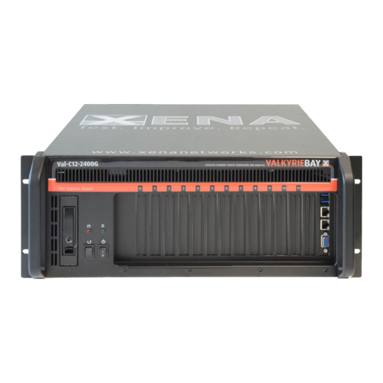
SPECIFICATIONS The ValkyrieBay is a 12-slot, 4U heavy-duty steel rack mount chassis designed to operate reliably in industrial environments. This guide describes the installation of modules in: • Val-C12-2400G – used for modules operating at all speeds from 40GE and up •... -
Page 3: Quick Overview
QUICK OVERVIEW Installing test modules in the ValkyrieBay chassis requires the following steps to be completed: Please take precautions to avoid any ESD damage by using EDS wrist strap or other precaution. Before opening the chassis, make sure to disconnect the power plug. - Page 4 For ports that are not in use, keep dust caps mounted. • Do not cover the front or rear ventilation openings in the chassis • Clean the chassis min. every 12 months to remove dust, using compressed air to ensure optimal • ventilation © Xena Networks – April 2021...
- Page 5 The installation steps outlined above are described in detail below. Please refer to the relevant section. STEP 1: Remove the top cover by unscrewing the two finger screws at the back of the chassis. STEP 2: Unscrew the restraining bar. © Xena Networks – April 2021...
- Page 6 Remove the air flow cover by unscrewing the two finger screws on top and sliding it backwards till it releases. STEP 4: Remove the alignment bar by loosening the two finger screws on top. © Xena Networks – April 2021...
- Page 7 STEP 5: Choose which slot the module should be mounted in and remove the bracket © Xena Networks – April 2021...
- Page 8 Slide the module into place and use the screw to secure it. Press the test module firmly but carefully into place – do not force it – and then fasten again with the screw from Step 3. © Xena Networks – April 2021...
- Page 9 Step 7 If needed (see list on page 3), connect 12 V power cable (Use delivered 12V cable) © Xena Networks – April 2021...
- Page 10 Mount the alignment bar by mounting the two finger screws. The alignment bar fixes the modules in place. Please make sure the top of the module goes into the appropriate slot in the alignment bar. © Xena Networks – April 2021...
- Page 11 Position the restraining bar in place and screw the restraining bar tightly in place. If sideways adjustments of the modules are necessary, we recommend doing it from right to left (Port 11 to Port © Xena Networks – April 2021...
- Page 12 STEP 11: Replace top lid and fasten it with the two finger screws (Do not operate the chassis without top lid) © Xena Networks – April 2021...
- Page 13 © Xena Networks – April 2021...
- Page 14 © Xena Networks – April 2021...
- Page 15 © Xena Networks – April 2021...
- Page 16 To minimize the risk of damage, please remove “long” test modules before transportation. This includes any test module(s) that extend past the metal restraining bar under the chassis lid. Always use the original Xena boxes for shipping (including the polystyrene foam and anti-static bags). © Xena Networks – April 2021...
Need help?
Do you have a question about the ValkyrieBay and is the answer not in the manual?
Questions and answers