Advertisement
Xena Networks ApS
XenaBay Chassis
Installation Guide
Version 1.0
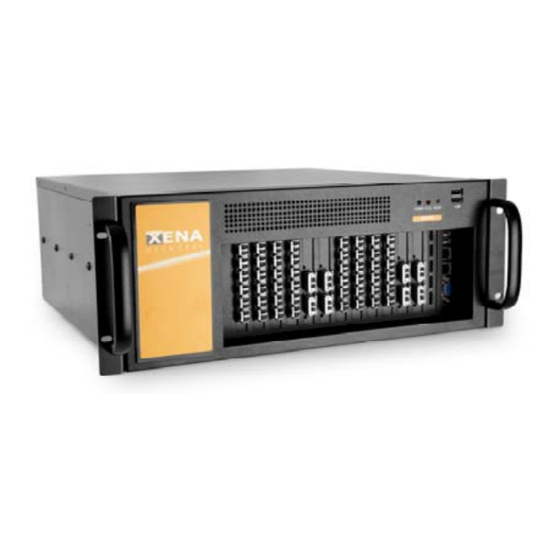
ABOUT THE XENABAY C4‐12 CHASSIS
The 4U, heavy-duty steel C4-12 rack mount
chassis is designed to operate reliably in
industrial environments
SPECIFICATIONS
Form Factor: Standard 4U, 19" wide
Construction: Metal
Slots Number: 12-slot
Cooling: 3 x 8cm Papst 8412NH / NGLE
Drive Bay: 1 x 2.5" internal HDD
Dimensions (DxWxH): 454.7 mm x 431mm x
176mm
Operating Temperature: 0~40°C
Relative Humidity: 5~95%
PACKING LIST
When you unpack the chassis, make sure
the following items have been shipped.
1 x Quick Installation Guide
1 x Power cord
2 x Handles and handle plates
Page 1
2009-11
Advertisement
Table of Contents

Related Manuals for Xena Networks XenaBay C4-12


Summary of Contents for Xena Networks XenaBay C4-12
- Page 1 Xena Networks ApS 2009-11 XenaBay Chassis Installation Guide Version 1.0 PACKING LIST ABOUT THE XENABAY C4‐12 CHASSIS When you unpack the chassis, make sure The 4U, heavy-duty steel C4-12 rack mount the following items have been shipped. chassis is designed to operate reliably in...
-
Page 2: Dimension Drawing
Xena Networks ApS 2009-11 DIMENSION DRAWING The dimensions of C4-12 are shown below. Figure 1 Dimension Drawing (measurement units: millimeter Page 2 ... -
Page 3: Installation Steps
Xena Networks ApS 2009-11 3.1: TOP COVER REMOVAL INSTALLATION STEPS The top cover is secured to the chassis with To install the C4-12 chassis, the following 6 retention screws, three on each side of the steps must be completed: chassis. To remove the top cover, please Unpack the chassis. -
Page 4: Cover Installation
Xena Networks ApS 2009-11 STEP 5: HOLD‐DOWN CLAMP AND COVER INSTALLATION To re-install the hold-down clamp, please follow the steps below: Slide the end of the hold-down Step a: clamp with 2 holes for the hold-down clamp hooks into the hold-down clamp securing hook on the right side of the chassis. -
Page 5: Chassis Maintenance
Xena Networks ApS 2009-11 CHASSIS MAINTENANCE • EPLACEMENT ________________________________ Please ensure that the power of the computer is switched off before fan replacement procedure. Figure 12 Remove the Fan Retention ________________________________ Screws There are three 8 cm cooling fans inside the C4-12... - Page 6 Xena Networks ApS 2009-11 Figure 14 Locations of the 4 Mounting Holes Page 6 ...
Need help?
Do you have a question about the XenaBay C4-12 and is the answer not in the manual?
Questions and answers