
Related Manuals for Ecoflam ECOMAX 3SC 80-N


Summary of Contents for Ecoflam ECOMAX 3SC 80-N
- Page 1 ECOMAX 3SC 80-N ÷ 6100-N www.ecoflam-burners.com INSTALLATION, USE AND MAINTENANCE (to be keep by the consumer) Technical data Operating instructions Electric diagrams Spare parts list 05/04/2018...
-
Page 2: Table Of Contents
4.4 Electrical wiring diagram of an elco three phase burner to the basic control panel................... 40 4.5 Electrical wiring diagram of an ecoflam single phase burner to the basic control panel ................41 4.6 Electrical wiring diagram of an elco three phase burner to the basic control panel.................. 42 4.9 Commissioning ...................................... -
Page 3: General Information
The appliance is intended to operate in hot air circulation heating systems. Any other use must be considered improper. Ecoflam shall not be held liable for any damage resulting from improper use; in this case the user is fully responsible for the risk. -
Page 4: Safety Warnings
General information 1.5 - SAFETY WARNINGS ATTENTION! The appliance must be installed, adjusted and maintained by professionally qualified personnel, in compliance with standards and provisions in force. Incorrect installation can cause damage to persons, animals and objects for which the manufacturer cannot be held responsible. DANGER! NEVER attempt performing maintenance or repairs on the boiler on your own initiative. -
Page 5: Technical Data Plate
General information 1.6 - TECHNICAL DATA PLATE The technical data plate is adhesive and is included in the document case; it must be applied by the installer on the outside of the casing. The serial number of the boiler is on the riveted plaque on the front plate of the body (front right top side). CE marking The CE marking certifies that the boilers meet: The essential requirements of the gas appliance directive... -
Page 6: General Warnings
Any repairs must be performed solely by personnel authorised as they provide important guidelines regarding installation, use by Ecoflam using original spare parts only. Failure to comply with and maintenance safety. the above can jeopardise the safety of the appliance. -
Page 7: Technical Features And Dimensions
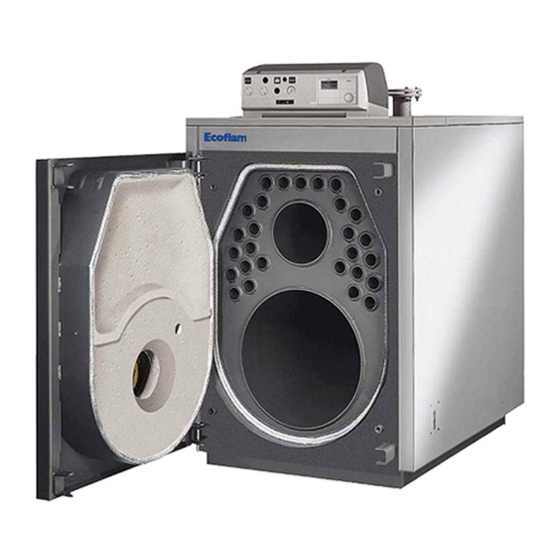
Technical features and dimensions TECHNICAL FEATURES AND DIMENSIONS 2.1 - TECHNICAL FEATURES ECOMAX 3SC boilers are the horizontal cylindrical type with model 3500-N), in turn protected by a mineral fibre fabric. flame inversion in furnace and third flue gas pass in tubes. From models from 3900-N to 6100-N the outer shell is covered The construction fully complies with prescriptions laid down in with a lamella mat 50 mm thick, in turn protected by an aluminium... -
Page 8: Smoke Turbulators
Technical features and dimensions 2.3 - SMOKE TURBULATORS ECOMAX 3SC boilers are designed to be used within an output range in order to improve seasonal efficiency and coupling with each heating system. The heat output must therefore be adjusted upon commissioning, based on the guidelines of the Thermotechnical Engineer, and always within the range provided for each boiler on pages 9 -... -
Page 9: Dimensions
Technical features and dimensions 2.4 - DIMENSIONS - ECOMAX 3SC 80-N÷250-N T1 T2-T5 fig. 3 1 Panel board T1 Heating flow T5 Boiler drain 2 Burner connection flange T2 Heating return T6 Condensation drain 3 Smoke chamber cleaning door T3 Chimney connection... - Page 10 Technical features and dimensions ECOMAX 3SC 300-N÷560-N T2-T3-T1 fig. 6 1 Panel board T1 Heating flow T5 Chimney connection 2 Burner connection flange T2 Heating return T6 Burner connection 3 Smoke chamber cleaning door T3 Expansion vessel connection T7 Condensation drain 4 Flame control warning light T4 Boiler drain ECOMAX 3SC...
- Page 11 Technical features and dimensions ECOMAX 3SC 680-N÷870-N T2-T3-T1 fig. 8 1 Panel board T1 Heating flow T5 Chimney connection 2 Burner connection flange T2 Heating return T6 Burner connection 3 Smoke chamber cleaning door T3 Expansion vessel connection T7 Condensation drain 4 Flame control warning light T4 Boiler drain CONNECTIONS...
- Page 12 Technical features and dimensions ECOMAX 3SC 1000-N÷2350-N T3-T2-T1 fig. 10 T9 Condensation drain 1 Panel board T1 Heating flow T5 Chimney connection 2 Burner connection flange T2 Heating return T6 Burner connection 3 Smoke chamber cleaning door T3 Expansion vessel connection T7 Boiler air bleed 4 Flame sight glass T4 Boiler drain...
- Page 13 Technical features and dimensions ECOMAX 3SC 2700-N÷3500-N fig. 14 1 Panel board T5 Chimney connection T9 Condensation drain T1 Heating flow 2 Burner connection flange T6 Burner connection T2 Heating return 3 Smoke chamber cleaning door T7 Boiler air bleed T3 Expansion vessel connection 4 Flame sight glass T8 Inspection door...
- Page 14 Technical features and dimensions ECOMAX 3SC 3900-N÷6100-N T1-T3-T2 fig. 17 1 Panel board T1 Heating flow T5 Chimney connection 2 Burner connection flange T2 Heating return T6 Burner connection 3 Smoke chamber cleaning door T3 Expansion vessel connection T7 Inspection door 4 Flame sight glass T4 Boiler drain T8 Condensation drain...
-
Page 15: Operating Data According To Uni 10348
Technical features and dimensions... - Page 16 Technical features and dimensions...
-
Page 17: Installation Instructions
Installation instructions INSTALLATION INSTRUCTIONS 3.1 - GENERAL WARNINGS ATTENTION! In rooms with the presence of aggressive vapours or dust, the appliance must operate ATTENTION! independently from the air inside the This boiler is intended solely for the use installation room! for which it was expressly designed. -
Page 18: Installation Standards
Installation instructions 3.2 - INSTALLATION STANDARDS Installation standard IEC 64-8 / II ed. The appliance must be installed in compliance with the Electric systems in buildings intended for residential and similar instructions provided in this manual. use. It must be installed by a professionally qualified technician, who Approval art. -
Page 19: Handling
Installation instructions 3.3 - HANDLING The boiler can be handled easily, lifting it by means If necessary for clearance purposes, the door and the smoke of upper hook/s or shifting it on rollers underneath chamber can be removed to make it easier to enter the boiler the sturdy base longerons. -
Page 20: Installing The Burner
Installation instructions The manufacturing companies of the burners can supply the øA BOILER TYPE dimensions of the flames which their appliances develop, especially those approved based on the standards indicated 80-N above. 120-N÷250-N Further information is provided in the chapter “Commissioning”. 300-N÷560-N 680-N÷870-N 1000-N÷1180-N... -
Page 21: Furnace Door: Adjustment, Opening, Closing
Installation instructions 3.7 - FURNACE DOOR: ADJUSTMENT, OPENING AND CLOSING IMPORTANT - The door of the boiler must be opened when it is cooled off to avoid damaging the fibre due to thermal shock. - The insulation fibre of the door can show cracks after a short time of operation;... -
Page 22: 680-N÷870-N Boilers
Installation instructions 3.7.3 - “680-N÷870-N” BOILERS For all these models, the door is hinged and fixed according to the layout in fig. 24. In these cases, the two hinges on the left are normally used as rotation hinges (from right to left) while the two on the right are used as closing hinges. -
Page 23: Connecting Flue Exhaust Pipe
Installation instructions 3.8 - CONNECTING FLUE EXHAUST PIPE To connect the flue gas exhaust pipe, local and national Use only exhaust pipes suitable for the type standards must be respected (see Standards UNI-CIG 7129 of fuel used. point 4 and 7131 point 5). The supplier will have no contractual or extra- The ECOMAX 3SC boiler can be attached to the chimney in contractual liability for damage caused due... -
Page 24: Connecting Boiler To System
This could damage the gaskets a short amount of time. and cause noise during operation. Ecoflam will not be held liable for damage to persons, animals or objects due to failure to Heating system safety valve discharge comply with the instruction above. -
Page 25: Gas Connection
Installation instructions As a precaution against gas leaks, we after commissioning the boiler and bringing the system to recommend installing a monitoring and the operating temperature, stop the pumps and repeat the air bleed operations; protection system consisting of a gas leak let the system cool off and, if necessary, return the water detector coupled with a shut-off solenoid pressure to 1 bar. -
Page 26: Packaging
Ecoflam will not be held liable for damage to The casing of boilers from 80-N to 450-N, complete with persons, animals or objects due to failure to comply insulation mattresses, is contained in one box. -
Page 27: Assembly Of Casing
Installation instructions 3.13 - ASSEMBLY OF CASING ECOMAX 3SC 80-N÷250-N fig. 27 Assembly sequence (Ref. fig. 27 and 28) A) Mount the insulation (pos. 1) of the boiler body and secure E) Fix the reinforcement pos. 6, to the top panel pos. 5 and press the 2 edges with the contact springs (pos. - Page 28 Installation instructions 1 Thermometer probe 2 Working thermostat probe 3 Safety thermostat probe 4 Minimum thermostat probe 5 Probe bulb holders fig. 28 6 Capillaries fixing spring Assembly sequence (Ref. fig. 29) A) Mount the insulation (pos. 1) of the boiler body and secure the 2 edges with the elastic straps (pos.
- Page 29 Installation instructions ECOMAX 3SC 340-N÷560-N fig. 29 4 11 1 Thermometer probe 2 Working thermostat probe 3 Safety thermostat probe fig. 30 4 Minimum thermostat probe 5 Safety spring 6 Contact spring...
- Page 30 Installation instructions Assembly sequence (Ref. fig. 31) A) Mount the insulation (pos. 1) of the boiler body and secure E) Insert into the conduits the bulbs of the instrumentsire nelle the 2 edges with the elastic straps (pos. 2) supplied in the guaine i bulbi degli strumenti come indicato in Fig.
- Page 31 Installation instructions Assembly sequence (Ref. fig. 32) A) Mount the insulation (pos. 1) of the boiler body and secure Close the cover of the electric control board. the 2 edges with the elastic straps (pos. 2) supplied in the Guide the burner plug through the side plate (pos. 5) on the accessory box, hooking them to the external fabric part of the preferred side and secure the cable with the cable gland insulation.
- Page 32 Installation instructions ECOMAX 3SC 2350-N fig. 33 Assembly sequence (Ref. fig. 33) A) Mount the insulation (pos. 1) of the boiler body and secure Close the cover of the electric control board. the 2 edges with the elastic straps (pos. 2) supplied in the Guide the burner plug through the side plate (pos.
- Page 33 Installation instructions ECOMAX 3SC 2700-N - 3500-N fig. 34 Assembly sequence (Ref. fig. 34) A) Mount the insulation (pos. 1) of the boiler body and secure D) Fix the panel board to the side panel (pos. 6. the 2 edges with the elastic straps supplied in the accessory Rotate the cover of the panel board frontwards after having box, hooking them to the external fabric part of the insulation.
- Page 34 Installation instructions Probe insertion sequence Following this sequence, insert the probes of the instruments in the bulb holder/s on the top of the boiler (Ref. fig. 35): of the thermometer (pos.1), of the working thermostat (pos. 2), of the safety thermostat (pos. 3), of the minimum thermostat (pos. 4). It is recommended to insert the probes all the way in the relative bulb holders for best contact.
- Page 35 Installation instructions Assembly sequence (Ref. fig. 36) The ECOMAX 3SC 3900-N ÷ ECOMAX 3SC 6100-N boilers are supplied with casing, for the mounting of the panel board, Insert the thermostat probe capillaries in the tube designed do the following: for their passage, that is placed under the casing (see detail “A”).
-
Page 36: Electrical Connections
Installation instructions 3.14 - ELECTRICAL CONNECTIONS 230V electric power supply connection The electrical connections are illustrated in chap. 3.16, 3.17, General warnings 3.18, 3.19, 3.21. The electrical safety of the appliance is guaranteed only when it has been properly connected to an efficient earthing system The boiler installation requires a connection to a 230 V - 50 Hz carried out as intended by safety standards in force: pipes of electric mains: this connection must be properly carried out as... -
Page 37: Standard Panel Board
Installation instructions STANDARD PANEL BOARD 4.1 - PANEL BOARD FUNCTIONS DESCRIPTION Through the main switch 11 the panel board and all the equipments connected to it will be under power. The switches 12 & 13 switch On and OFF the power to the burner and the Heating pump (via a relay, if necessary). -
Page 38: Electrical Wiring Diagram Of Ageneric Burner To The Basic Control Panel
Installation instructions 4.2 ELECTRICAL WIRING DIAGRAM OF A GENERIC BURNER TO THE BASIC CONTROL PANEL thermostatic line block signal (MAX OUTPUT burner operating signal CONTACTS 1A) consensus high-low flame thermostat ~ 50Hz 230V power supply to GENERIC BURNER the burner 13 14 19 20 21 BOILER CONTROL BOX... -
Page 39: Electrical Wiring Diagram Of An Elco Single Phase Burner To The Basic Control Panel
Installation instructions ELECTRICAL WIRING DIAGRAM OF AN ELCO SINGLE PHASE BURNER TO THE BASIC CONTROL PANEL BURNER ELECTRICAL CONNECTION T1 N T8 T7 T6 T1 N T8 T7 T6 (MAX OUTPUT CONTACTS 1A) ~ 50Hz 230V BOILER CONTROL 13 14 19 20 21 FU FUSE STAB... -
Page 40: Electrical Wiring Diagram Of An Elco Three Phase Burner To The Basic Control Panel
Installation instructions ELECTRICAL WIRING DIAGRAM OF AN ELCO THREE PHASE BURNER TO THE BASIC CONTROL PANEL BURNER ELECTRICAL 297 296 178 86 85 84 73 51C L3 L2 L1 CONNECTION ~50 Hz 400V by the installer T6 B5 B4 S3 T2 T1 N ACCESSORY WIRING S3 T2 ACCESSORY... -
Page 41: Electrical Wiring Diagram Of An Ecoflam Single Phase Burner To The Basic Control Panel
Installation instructions ELECTRICAL WIRING DIAGRAM OF AN ECOFLAM SINGLE PHASE BURNER TO THE BASIC CONTROL PANEL ECOFLAM BURNER CONTROL BOX FOR MAX 11 12 MAX GAS 350 P / PAB / PR / MD BOILER CONTROL BOX CONNECTION CABLES FOR MAX... -
Page 42: Electrical Wiring Diagram Of An Elco Three Phase Burner To The Basic Control Panel
Installation instructions ELECTRICAL WIRING DIAGRAM OF AN ELCO THREE PHASE BURNER TO THE BASIC CONTROL PANEL Before connecting the wires, remove the bridges 1-3 and 2-4 BURNER BURNER 11 12 ELECTRICAL ELECTRICAL CONNECTION CONNECTION ~50 Hz 400V TRIPHASE WIRING CONNECTION (ACCESSORY) T6 B5 B4 S3 T2 T1 N... -
Page 43: Commissioning
C o m m i s s i o n i n g m u s t b e d o n e b y Information for system manager professionally qualified personnel. Ecoflam will not be held liable for damage to persons,... -
Page 44: Adjusting The Burner
Installation instructions 4.10 - ADJUSTING THE BURNER The following instructions are intended When the burner is adjusted properly, the following values should exclusively for service personnel authorised be obtained, measured at the chimney by a specific analyser. by the manufacturer of the burner. With natural gas: - CO... -
Page 45: Inspection And Maintenance
Ecoflam spare parts must be used. its long life. Yearly maintenance of the appliance is Before proceeding with maintenance, always perform the mandatory in compliance with Laws in force. -
Page 46: Boiler Body Maintenance
Installation instructions Boiler body maintenance Check condition of gaskets and insulation fibres The insulation fibre of the door can show cracks Danger! after a short time of operation; this however does Before performing any maintenance, make not reduce its insulation capacity nor jeopardise sure the boiler and its components have its lifespan. - Page 48 Ecoflam Bruciatori S.p.A. reserves the right to make any adjustments, without prior notice, which is considered necessary or useful to its products, without affecting their main features Ecoflam Bruciatori S.p.A. si riserva il diritto di apportare ai prodotti le modifiche che riterrà necessarie o utili, senza pregiudicarne le caratteristiche principali.
Need help?
Do you have a question about the ECOMAX 3SC 80-N and is the answer not in the manual?
Questions and answers