Daikin FCAHG71HVEB Installation And Operation Manual
Split system air conditioners
Hide thumbs
Also See for FCAHG71HVEB:
- Installer and user reference manual (84 pages) ,
- Manual (32 pages)

Related Manuals for Daikin FCAHG71HVEB


Summary of Contents for Daikin FCAHG71HVEB
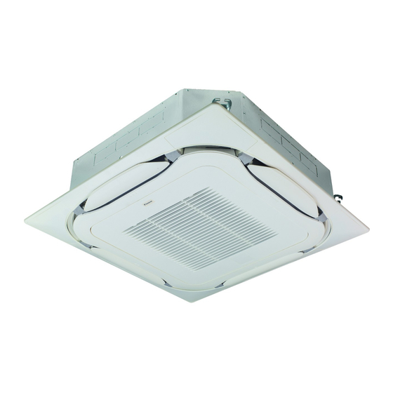
- Page 1 Installation and operation manual Split system air conditioners FCAHG71HVEB FCAHG100HVEB Installation and operation manual FCAHG125HVEB English Split system air conditioners FCAHG140HVEB...
- Page 2 3P480520-13D...
-
Page 3: Table Of Contents
Using the dry program............... 14 Daikin website (publicly accessible). 12.3.1 About the dry program ..........14 ▪ The full set of latest technical data is available on the Daikin 12.3.2 To use the dry program..........14 extranet (authentication required). 12.4 Adjusting the air flow direction........... -
Page 4: For The Installer
2 About the box For the installer CAUTION About the box Appliance not accessible to the general public, install it in a secured area, protected from easy access. Indoor unit This unit, both indoor and outdoor, is suitable for installation commercial light industrial... -
Page 5: Installation
4 Installation Paper pattern for installation (upper part of the packing) Installation Screws (accessories) ▪ Ceiling opening and unit: Mounting the indoor unit ▪ Make sure the ceiling opening is within the following limits: Minimum: 860 mm to be able to fit the unit. 4.1.1 Guidelines when installing the indoor unit Maximum: 910 ... -
Page 6: Guidelines When Installing The Drain Piping
4 Installation Hanging bars (field supply) ▪ Level. Make sure the unit is level at all 4 corners using a level or a water-filled vinyl tube. ▪ Condensation. Take measures against condensation. Insulate the complete drain piping in the building. ▪... -
Page 7: Connecting The Refrigerant Piping
4 Installation ▪ Remove the switch box cover (a). 4.2.1 To connect the refrigerant piping to the ▪ Connect the user interface (b). indoor unit ▪ Connect the power supply (1~ 220-240 V 50/60 Hz) and earth (c). CAUTION ▪ Reattach the switch box cover (a). Install the refrigerating piping or components in a position where they are unlikely to be exposed to any substance which may corrode components containing refrigerant,... -
Page 8: Specifications Of Standard Wiring Components
5 Configuration 1~ 50 Hz 4.3.1 Specifications of standard wiring 220-240 V components Component Specification Interconnection cable 4-core cable (indoor↔outdoor) 1.5 mm ~2.5 mm applicable for 220~240 V H05RN-F (60245 IEC 57) User interface cable Vinyl cords with 0.75 to 1.25 mm² sheath or cables (2‑core wires) Maximum 500 m H03VV-F (60227 IEC 52) - Page 9 5 Configuration Setting: Time to clean air filter If the distance to the floor is (m) Then This setting must correspond with the air contamination in the room. FCAHG71 FCAHG100~140 It determines the interval at which the TIME TO CLEAN AIR FILTER ≤2.7 ≤3.2 13 (23)
-
Page 10: Commissioning
6 Commissioning 1~ 50 Hz To perform a test run 220-240 V This task is only applicable when using the BRC1E52 or BRC1E53 user interface. When using any other user interface, see the installation manual or service manual of the user interface. NOTICE Do not interrupt the test run. -
Page 11: Error Codes When Performing A Test Run
▪ A subset of the latest technical data is available on the regional Daikin website (publicly accessible). ▪ The full set of latest technical data is available on the Daikin extranet (authentication required). Error codes when performing a... -
Page 12: For The User
9 About the system Indoor unit Terminal strip Swing motor INDOOR MR*, MRCW*, MRM*, MRN* Magnetic relay Outdoor unit Wire clamp Neutral OUTDOOR n=*, N=* Number of passes through ferrite Colors: core Pulse-amplitude modulation Black Orange PCB* Printed circuit board Blue Pink Power module... -
Page 13: User Interface
10 User interface NOTICE Operation For future modifications or expansions of your system: A full overview of allowable combinations (for future 12.1 Operation range system extensions) is available in technical engineering data and should be consulted. Contact your installer to Use the system in the following temperature and humidity ranges for receive more information and professional advice. -
Page 14: To Operate The System
12 Operation The indoor unit will indicate defrost operation on the display Cooling Heating ▪ When the room temperature is ▪ When starting operation. Hot start lower than ▪ When the room temperature is In order to prevent cold air from blowing out of an indoor unit at the temperature. -
Page 15: Maintenance And Service
13 Maintenance and service Go to the home screen. 13.2 Cleaning the air filter, suction Cool Set to grille, air outlet and outside panels °C CAUTION Turn off the unit before cleaning the air filter, suction grille, Check if Air Volume/direction Air Volume/direction air outlet and outside panels. -
Page 16: To Clean The Suction Grille
13 Maintenance and service 4 Clean the suction grille. Wash with a soft bristle brush, and water or neutral detergent. If the suction grille is very dirty, use a typical kitchen cleaner, leave it on for 10 min, then wash it 4 Dry the air filter in the shadow. - Page 17 14 Troubleshooting Refrigerant type: R410A Malfunction Measure Global warming potential (GWP) value: 2087.5 If the user interface display indicates the Notify your installer and unit number, the operation lamp flashes report the malfunction NOTICE and the malfunction code appears. code. Applicable legislation on fluorinated greenhouse gases If the system does NOT properly operate except for the above requires that the refrigerant charge of the unit is indicated...
- Page 20 4P535639-1B 2019.01...
Need help?
Do you have a question about the FCAHG71HVEB and is the answer not in the manual?
Questions and answers