Table of Contents
Advertisement
Quick Links
Advertisement
Table of Contents

Related Manuals for CleverMic Pro HD PTZ HUSL20


Summary of Contents for CleverMic Pro HD PTZ HUSL20
- Page 1 CleverMic Pro HD PTZ HUSL20 User Manual Version V1.0 (English)...
-
Page 2: Table Of Contents
CONTENT CONTENT ......................................1 SAFETY GUIDES ....................................2 PACKING LIST....................................... 3 QUICK START ....................................... 3 PRODUCT HIGHLIGHTS..................................4 CAMERA SPEC..................................... 4 CAMERA INTERFACE.................................... 6 CAMERA DIMENSION..................................6 IR REMOTE CONTROLLER..................................7 VISCA(RS232)PORT..................................9 VISCA PROTOCOL ........................ОШИБКА! ЗАКЛАДКА НЕ ОПРЕДЕЛЕНА. PELCO-D PROTOCOL .................................. -
Page 3: Safety Guides
SAFETY GUIDES 1.Before operation, please fully read and follow all instructions in the manual. For your safety, always keep this manual with the camera. 2.The camera power input range is 100-240VAC(50-60Hz),ensure the power supply input within this rate before powering on. 3.The camera power voltage is 12VDC, rated currency is 2A. -
Page 4: Packing List
PACKING LIST Check all bellow items when open the package: Camera ············································································································· 1 Power Adapter ·································································································· 1 Power Cable······································································································ 1 RS232 Control Cable ························································································· 1 USB3.0 Cable ···································································································· 1 Remote Controller ···························································································· 1 User Manual ····································································································· 1 Double-sided Adhesive ····················································································· 1 QC certification ·································································································... -
Page 5: Product Highlights
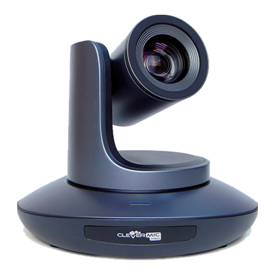
PRODUCT HIGHLIGHTS Adopts most advanced ISP, 1/2.8 inch 5MP sensor, providing full HD video resolution and crystal clear image. High end 20x optical zoom, 2x digital zoom lens with 60 degree field of view. IP, HDMI, 3G-SDI, USB video outputs interface, fit for different application ... - Page 6 Zoom F4.9~98mm(20X), F1.5 – 3.0, View Angle:60°(Far)-3.2°(Near) Rotation Angle Pan: -170° ~ +170°; Tilt: -30° ~ +90° Rotation Speed Pan: 0°~120°/s ; Tilt: 0°~80°/s Preset: Remote controller: 10; RS232: 128; Accuracy: 0.1° Control Port RS232、RS485(optional)、RJ45 (VISCA over IP)、USB3.0(UVC1.5) Network Speed 1000M Video encode H.264/H.265(default: H.264)
-
Page 7: Camera Interface
CAMERA INTERFACE 1.Camera Lens 6. Tripod Screw Hole 10. HDMI port 2.Camera Base 7. Installation Hole 11.3G-SDI port 3.IR Receiver Panel 8. RS232 control port (input) 12, USB port 4.Power Indicator Light 9. RS232 control port(output) 13, RJ45 port 5.Dial Switch 14. -
Page 8: Ir Remote Controller
IR REMOTE CONTROLLER POWER Under normal working mode, short press POWER key, to enter standby mode; Press it again, the camera will do self-configuration, then go back to HOME position. It will go to preset position if power on model has been set before. FREEZE (Not Supported in USB)... - Page 9 FOCUS KEY ( ON THE LEFT) Manual focus, only valid under manual focus model. ZOOM KEY( ON THE RIGHT SIDE) Set the zoom rate NAVIGATE KEY: UP/DOWN/LEFT/RIGHT Under working mode, use navigate key to set the pan tilt, and select menu when enter OSD.
-
Page 10: Visca(Rs232)Port
VISCA IN (RS232 PORT) V_IN V_OUT VISCA IN RS485 A(+) IR OUT IR OUT B(-) VISCA IN &Mini DIN Connection VISCA IN & DB9 Connection Camera VISCA IN Camera VISCA IN Windows DB-9 Mini DIN A(+) A(+) IR OUT IR OUT B(-) B(-) VISCA Network Construction:... -
Page 11: Visca Protocol
Parameter Value Parameter Value Baud rate 2400/4800/9600/115200 Stop Bit 1bit Start Bit 1 bit Check Bit None Date Bit 8 bit VISCA PROTOCOL Part1 Camera Return Command Ack/Completion Message Command Packet Note z0 41 FF Returned when the command is accepted. Completion z0 51 FF Returned when the command has been executed. - Page 12 Command type function Command packet Note CAM_Focus Far(Standard) 8x 01 04 08 02 FF Near(Standard) 8x 01 04 08 03 FF Far (Variable) 81 01 04 08 2p FF p=0 (Low) to 7 (High) Near (Variable) 81 01 04 08 3p FF p=0 (Low) to 7 (High) Direct 8x 01 04 48 0p 0q 0r 0s FF...
- Page 13 Command type function Command packet Note Reset 8x 01 04 0A 00 FF 8x 01 04 0A 02 FF Shutter Setting CAM_Shutter Down 8x 01 04 0A 03 FF Direct 8x 01 04 4A 00 00 0p 0q FF pq: Shutter Position (0~0x15) Reset 8x 01 04 0B 00 FF...
- Page 14 Command type function Command packet Note CAM_Saturation Saturation 8x 01 04 A1 00 00 0p 0q FF pq :saturation level 0x00~0xff CAM_Contrast Contrast 8x 01 04 A2 00 00 0p 0q FF pq :Contrast level 0x00~0xff 8x 01 06 A0 02 FF CAM_SpeedByZoo 8x 01 06 A0 03 FF CAM_PTSpeed...
- Page 15 Command type function Command packet Note 720P30 0x0e 720P25 0x11 1080P5994 0x13 1080I5994 0x02 1080P2997 0x07 720P5994 0x0a 720P2997 0x0f 1080P24 0x2a 1080P2398 0x2b 4K@30 0x1D 4K@25 0x1E CAM_IDWrite 8x 01 04 22 0p 0q 0r 0s FF pqrs: Camera ID (=0000 to FFFF) DHCP off 8x 01 04 AE 00 FF DHCP off...
- Page 16 Command type function Command packet Note brightness balance OFF 8x 01 04 B7 00 FF Keep Brightness brightness balance ON 8x 01 04 B7 01 FF No keep Brightness Flare mode red value Flare red 8x 01 04 B8 dat FF Default is 32 Flare mode green value Flare green...
- Page 17 y0 50 03 FF Off(Standby) CAM_ZoomPosInq 8x 09 04 47 FF y0 50 0p 0q 0r 0s FF pqrs: Zoom Position y0 50 02 FF Auto Focus CAM_FocusModeInq 8x 09 04 38 FF y0 50 03 FF Manual Focus CAM_FocusPosInq 8x 09 04 48 FF y0 50 0p 0q 0r 0s FF pqrs: Focus Position...
- Page 18 y0 50 03 FF y0 07 7D 01 04 00 FF Power ON/OFF y0 07 7D 01 04 07 FF Zoom tele/wide y0 07 7D 01 04 38 FF AF On/Off IR_ReceiveReturn y0 07 7D 01 04 33 FF CAM_Backlight y0 07 7D 01 04 3F FF CAM_Memory y0 07 7D 01 06 01 FF...
-
Page 19: Pelco-D Protocol
PELCO-D Protocol Command List Function Byte1 Byte2 Byte3 Byte4 Byte5 Byte6 Byte7 0xFF Address 0x00 0x08 Pan Speed Tilt Speed Down 0xFF Address 0x00 0x10 Pan Speed Tilt Speed Left 0xFF Address 0x00 0x04 Pan Speed Tilt Speed Right 0xFF Address 0x00 0x02... -
Page 20: Pelco-P Protocol
PELCO-P Protocol Command List Function Byte1 Byte2 Byte3 Byte4 Byte5 Byte6 Byte7 Byte8 0Xa0 Address 0x00 0x08 Pan Speed Tilt Speed 0Xaf Down 0Xa0 Address 0x00 0x10 Pan Speed Tilt Speed 0Xaf Left 0Xa0 Address 0x00 0x04 Pan Speed Tilt Speed 0Xaf Right 0Xa0... -
Page 21: Osd Menu
OSD MENU 1. Under working mode, press the MENU key on the IR remote controller, to enter the OSD menu as bellow: 2, After enter the main menu, use the navigate UP/DOWN key to select the main menu. Once been selected, the main menu will change to blue background, and the right side will show all sub menu options. - Page 22 GAMMA Gamma curve selection Default:0 RETURN Return to previous menu Optional: AUTO、 INDOOR、 OUTDOOR、 MANUAL、 OUTAUTO、 SODIUM WB MODE Default:ATW LAMP AUTO 、SODIUM LAMP R GAIN Red gain level: 0~255, only valid under manual white balance mode. Default:AUTO IMAGE B GAIN Blue gain level:0~255 , only valid under manual white balance mode Default:AUTO DEFOG...
- Page 23 1080P30 720P60 720P50 720P30 720P25 Return CAM RESET Reset camera parameter to default RESET PTZ RESET Reset pan/tilt parameter to default ALL RESET Reset all parameter to default RETURN Return to the previous menu CONTROL VER Camera control firmware version CONTROL DATE Camera control firmware releasing date FORMAT...
-
Page 24: Uvc Control
UVC CONTROL 1. Only run the client software after the USB3.0 camera has completed self-configuration (the IR indicator in blue color and will not flash); otherwise may cause black video issue. 2. Make sure the USB3.0 camera is recognized by the PC Device Manager. 3.Make sure the interval of video format switching more than 3 seconds, otherwise black video maybe caused. -
Page 25: Web Setting
WEB SETTING Download Active-X to install When visit IP camera via Internet Explore browser the first time, the system will install camera Active-X automatically. How to install Input IP camera address in IE, the default address is 192.168.1.188, to enter into login page, the system will indicate to install Active-X as following, and then press “Allow installing”... - Page 26 Login Once install Active-X, reopen IE browser, and enter into IP address, to login interface, input admin and password to login as following: Default admin: admin Default password: admin Real-time Preview: Preview interface as above image, on the right side, there are options to control camera pan, tilt, zoom, focus, presets, focus speed, zoom speed can be set.
- Page 27 Parameter Setting Click “Setting” to enter into parameter setting interafeace as following: “Video Encode”: can set image encode mode, main stream and sub stream resolution/bit rate/frame rate, bit rate control way, and I frame interval etc as above image “Image Parameter”can set focus, exposure, white balance, image, image quality, noise-reduction, as following picture...
- Page 28 Focus including focus mode, default focal distance, digital zoom etc Exposure includes exposure mode, shutter speed, gain, iris, brightness, and anti-flicker. White Balance includes white balance mode, red gain, blue gain. Image includes mirror, flip, backlight compensation, Gamma, WDR(wide dynamic range). WDR parameter can be set when it is ON.
- Page 29 “Ethernet” includes DHCP mode, IP address, subnet mask, default gateway, http port, web port, main stream port, sub stream port. Default parameter as following: DHCP HTTP port IP address 192.168.1.188 Web port 6087 Subnet mask 255.255.255.0 Main stream port Default gateway 192.168.1.1 Sub stream port “Firmware upgrade”: it is for camera program upgrade, currently only for ISP part update.
- Page 30 Reset to default is to reset the camera in default setting Reset simply: reset camera image parameter Reset all: reset camera Ethernet and image parameter, language and protocol will not be reset. Reboot: Reboot ISP part of camera...
- Page 31 Account is used for setting camera account and password Input the account firstly, then input same password twice, click set to finish Please remember account and password, otherwise you may be not able to login.
- Page 32 Using VCL to view RTSP Video Default RTSP main streaming address: rtsp://192.168.1.188/stream/main Default RTSP sub streaming address: rtsp://192.168.1.188/stream/sub 1, Open VLC media player 2, Media->network stream, to enter into “open media” interface. 3, Input RTSP address in URL as following: 4, Click play to view the real time image.
-
Page 33: Visca Over Ip
VISCA over IP VISCA over IP means VISCA protocol transmit via IP, to reduce RS232/RS485 cable layout (the controller must support IP communication function) Communication port spec: Control port: RJ45 Gigabit LAN IP protocol: IPv4 Transmit protocol: UDP ... - Page 34 Payload type: Data definition as following: Name Value (Byte 0) Value (Byte 0) Value (Byte 0) VISCA command 0x01 0x00 Stores the VISCA command. VISCA inquiry 0x01 0x10 Stores the VISCA inquiry. Stores the reply for the VISCA command and VISCA VISCA reply 0x01 0x11...
- Page 35 Controlled reply The following data is saved in return command payload of control command. Delivery confirmation VISCA over IP uses UDP as transmission communication protocol, UDP communication message transmission is not stable, it is necessary to confirm delivery and resent in application. Generally, when controller sends a command to peripheral equipment, controller will wait for the return message then send the next command, we can detect and confirm if the peripheral equipment receive the commands from return message’s lag time.
- Page 36 Sequence chart as following Sequence chart when returned message lost Sequence chart when command lost Note: Do not set IP address, subnet mask, gateway parameter in VISCA over IP command, otherwise, it will cause network breaks off. Due to change these parameter, network will be in off status.
Need help?
Do you have a question about the Pro HD PTZ HUSL20 and is the answer not in the manual?
Questions and answers