
Related Manuals for Vintage Model Co MAGNIFICENT FLYING MACHINES DE HAVILLAND TIGER MOTH


Summary of Contents for Vintage Model Co MAGNIFICENT FLYING MACHINES DE HAVILLAND TIGER MOTH
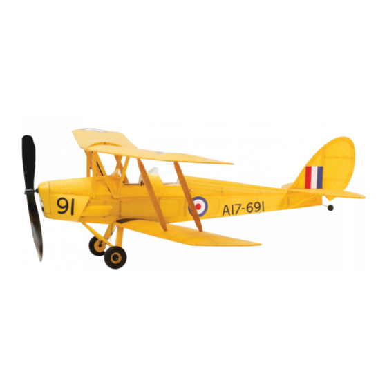
- Page 1 DE HAVILLAND TIGER MOTH VMC Instruction Booklet - Tiger Moth JAN19.indd 1 19/01/2019 12:26...
- Page 2 vintagemodelcompany.com VMC Instruction Booklet - Tiger Moth JAN19.indd 2 19/01/2019 12:26...
- Page 3 THE DE HAVILLAND TIGER MOTH – THE AIRCRAFT THAT GAVE CHURCHILL’S FEW THEIR WINGS In the early 1930s the British Air Ministry issued Whether by accident or design, all of these changes a specification for a new trainer aircraft for the made the DH.82 Tiger Moth an excellent training RAF.
- Page 4 YOUR KIT This kit is designed for you to build a traditionally Power is provided by rubber strip motor that is constructed, rubber powered, free flight model of a wound up before flight. Free flight means just that – DH.82A Tiger Moth. The kit includes the materials once the model is launched, it is on its own.
-
Page 5: Kit Contents
Typically for a small model and in the spirit of the sensitivity so that the shape and spirit of the original traditional kits, profiles are simplified and adjusted aircraft is preserved as much as possible. Also in from the original and a relatively large propeller the spirit of the traditional kits, additional items is used. - Page 6 OTHER THINGS THAT YOU WILL NEED CONSUMABLES • Glue. ‘Cyano’ (sometimes called ‘superglue’), • Tissue sealant – if you want to fly your model quick setting epoxy and a ‘glue stick’. outdoors (see ‘Covering’ for details). • Cling film or waxed paper to cover your plan or a •...
- Page 7 THE PLAN, GENERAL BUILDING TECHNIQUES, TERMS, HINTS AND TIPS The plan provides most instructions for the • Cut through section: This is simply a way of construction of the major components. showing parts on the plan in more detail – as if you had cut through the parts on the line shown.
- Page 8 TIPS TO MAKE A GOOD JOB OF YOUR MODEL Read and follow the instructions and the plan carefully. foil from a yoghurt pot lid. Alternatively, save pistachio nut shells – one held upright and firm • A light model will fly much better than a heavy on a piece of Blu-Tack or plasticine makes an one, so use glues and adhesives sparingly.
- Page 9 • The balsa sheets are graded. Sheet 1 and 2 are hard after the parts are laser cut. and strong but heavy – they are used for parts where • You can work on several parts at one time. strength is in preference to weight. Sheets 3 and 4 For instance, you can make up the wheels and are weaker and softer but light and are used for parts undercarriage at the same time as something else...
- Page 10 MAIN PARTS AND FRAMES BUILDING SCHEDULE THE CENTRE SECTION ‘FUEL TANK’ 1) Identify and remove all of the parts on the laser 6) Now glue a TR2 rib to the outside of the TR1 cut sheets: CS1, CS2, CS3, TR1 and TR2 rib each side, lining it up with the extensions of (2 off each), and 4 off corner gussets.
- Page 11 THE MAIN WING PANELS There are obviously two sets of wings to build. of the cabane and inter-planar struts, etc., so On the Tiger Moth, the upper and lower wings are follow the instructions and the plan very carefully very similar apart from their shape/angles at the root to avoid mistakes.
- Page 12 8) Glue the corner gusset pieces W8U and W9U in 10) For both wings, round off the leading edges and position along with the light 1.6mm square strip taper the trailing edges as shown on the plan. pieces at the base of the ribs R3 as shown. These Carefully give the entire structure a light sanding strips bridge the slots where the cabane and to smooth the joints, remove lumps and bumps...
- Page 13 5) Fit and glue all of the remaining ribs making sure to both sides of the R4 rib as shown. These that they are upright and properly located in the parts bridge the slots where inter-planar struts lower spar, leading and trailing edges and rib R4 will fit later so make sure that no glue goes into is fitted in the correct position.
- Page 14 2) Referring to the wing decalage jig outlines on 5) Once the glue is set, remove the jig from the the plan, cut four pieces of 4.8mm wide strip to plan/board and mark it ‘inner’ to reduce the the lengths shown and set them aside (all four chance of a mix up later in the build.
- Page 15 THE TAIL PLANE (STABILIZER) NB. for both the tail plane and fin rudder, when light 4) Pin down the tail plane central spar T1. 1.6mm strip is required, use it carefully as at least 5) Lay out the parts starting at T6 and work round 6 full lengths are required for the completion of in each direction, making any small adjustments.
- Page 16 THE FIN AND RUDDER 1) Identify and remove all of the parts on the laser When you are satisfied, glue all the parts in position cut sheets: FR1-FR8 and a corner gusset. making sure that you have nice neat butt joints. Allow this outline to set.
- Page 17 THE FUSELAGE At this point the major side pieces of the fuselage 4) Referring to the plan, on each fuselage side (K1) should be very carefully handled as before the glue a piece of stiff 1.6mm square strip in the various stiffeners and other structural parts are slots beneath the K2 position to ‘bridge’...
- Page 18 FUSELAGE ASSEMBLY 1) As well as all of the parts as prepared in the 5) Bring the nose together fitting the F1 and F2 previous steps, identify and remove all of the assembly along with part K3. Take care to make parts on the laser cut sheets: K3, K4 (2 off), K5 sure that the tabs on the fuselage locate neatly F3, F8, F8A, F9, F9A and F10.
- Page 19 9) Fit formers and cross pieces F8, F8A, F9 and 14) Carefully cut two pieces of 4.8mm strip that will F9A top and bottom working backward ensuring go from side to side and form the slots for the that the fuselage remains square and true in undercarriage.
- Page 20 THE WHEELS, UNDERCARRIAGE AND TAIL SKID/WHEEL 1) Using wire cutters and pliers, make up the wire 5) Laminate the parts cross-grained as shown on pieces that constitute the main undercarriage the plan to make 2 wheels, making sure all of the and tail wheel/skid.
- Page 21 THE NOSE BLOCK 1) Remove parts in the following quantities from adjusting it to have an easy fit. Cyano adhesive the laser cut sheets: 1 off each NB1-NB6, and can be run around the fuselage hole and 2 off NP1. the edges of the part to harden the wood.
- Page 22 FINISHING THE FUSELAGE AND NOSE BLOCK 1) Fit the nose block, BUT DO NOT GLUE IT 3) Sand the bottom (angled) edge of the IN PLACE! Sand it to match the fuselage and strengthener and adjacent 4.8mm wide strip at to the profile as shown on the plan.
- Page 23 OIL TANK 1) Identify and remove parts from the laser cut 2) Make up the oil tank as shown on the plan, sheets: OT1 AND OT2. sanding it to the correct profile. REMAINING PARTS FOR USE IN THE ASSEMBLY OF THE MODEL After all of the previous building steps have been completed, there should be the following parts left on the laser cut sheets: 2 off each IS1, IS2, LG1,...
- Page 24 COVERING Clear lacquer This is available at many DIY stores The tissue in the kit is used to provide a ‘skin’ over the balsa wood framework. The basic idea is that in spray cans. The model can be given a single coat the tissue is attached to the framework and then of it once it is built, but before the paper decals are sprayed with water and then left to dry.
- Page 25 THE FIN, RUDDER AND TAIL PLANE 1) For the covering you will need a glue stick, gently tug and tease the tissue until there are no PVA, fine brush, scissors, an old perfume bottle wrinkles and the tissue is nice and smooth. You or fine mist sprayer and a sharp knife.
- Page 26 7) Spray the part with a fine mist of water on both warps. Note that the tissue is very delicate when sides, then use the spacers that you ‘sticky taped’ it is wet, so handle the part at the edges and with to hold the edge of the part off the board.
- Page 27 correctly aligned to both the centre section and 3) Repeat step 2 for the right wing panel. Leave the profile on the plan. Prop up the wing tip entire assembly to set before removing it from 9.5mm using a matchbox or similar. the building board.
- Page 28 THE FUSELAGE 1) Cover the fuselage in a similar way to the flying 3) Cut away any tissue to clear the slots and fit the cabane struts following the instructions surfaces using a glue stick and thinned PVA on on the plan. overlapping joints or where the glue stick cannot reach.
- Page 29 8) For both parts U, fold all of the tissue edges 14) Start with part X, which fits on the left hand side – back on themselves and glue to the rear of i.e. the view shown on the plan. Attach the part to the part to hide the wide edges of the paper.
-
Page 30: Final Assembly
FINAL ASSEMBLY 1) If you want to draw on the control surfaces, do so 7) Make slits in the tissue at the positions where now using a fine marker or strips of black paper the F3A and F5 stiffeners are i.e. where the referring to the chain dashed lines on the plan. - Page 31 12) Glue the fin and rudder in place, ensuring it is 16) Fit the motor peg made from the cocktail stick/ properly located on the tail plane and at right toothpick provided, cutting it to length and angles to it, adjusting it if required. leaving about 5mm sticking out each side.
- Page 32 TRIMMING AND FLYING YOUR MODEL When flying your model, choose a large area experienced free flight modellers who have websites free from any obstructions. Do not fly it towards dedicated to the subject or post information on people or property. numerous on-line forums.
- Page 33 TO MAKE UP AND FIT THE MOTOR The motor consists of the rubber strip provided. hole in the nose. Wetting the rubber makes it easier This strip is more refined than that used in rubber to tie a knot, however, do not pull the knot too tight bands and is very stretchy, allowing it to hold lots otherwise it can tear.
- Page 34 TEST GLIDES Choose a calm, dry day if you are trimming your Gently throw your model towards an imaginary model outdoors. This is a small model and slight point on the floor about 7-8 metres in front of you gusts and disturbances will make it hard to judge into any wind.
- Page 35 POWERED FLIGHTS Wind up the motor with approximately 50 turns spirals in, then add an acetate tab to the lower (wind clockwise looking at the front of the model) left hand wing and bend it down a little. Gradually and launch it into the direction of the wind (if increase the turns on the motor in steps of 50 turns present).
- Page 36 THANK YOU FOR CHOOSING A VINTAGE MODEL COMPANY KIT We hope that you have enjoyed building and flying your model. Be sure to collect and build the whole range, available from many high street gift shops or direct from our website www.vintagemodelcompany.com where you will also find a wide range of modelling accessories and tips.
-
Page 37: Building Notes
BUILDING NOTES Use this sheet for notes during your build Tiger Moth VMC Instruction Booklet - Tiger Moth JAN19.indd 37 19/01/2019 12:26... -
Page 38: Flight Log
FLIGHT LOG Keep a log of your flight durations here vintagemodelcompany.com VMC Instruction Booklet - Tiger Moth JAN19.indd 38 19/01/2019 12:26... - Page 39 Tiger Moth VMC Instruction Booklet - Tiger Moth JAN19.indd 39 19/01/2019 12:26...
- Page 40 vintagemodelcompany.com vintagemodelcompany.com VMC Instruction Booklet - Tiger Moth JAN19.indd 40 19/01/2019 12:26...
Need help?
Do you have a question about the MAGNIFICENT FLYING MACHINES DE HAVILLAND TIGER MOTH and is the answer not in the manual?
Questions and answers