Table of Contents
Advertisement
Quick Links
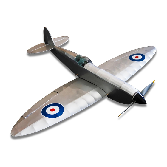
Balsa Basics Spitfire - Building Instructions.
Fuselage Construction
Build the motor and battery inner fuselage box.
1. If the standard 'B' type VMC* motor is being used (or similar), locate the motor mount 'F2-B' and former/
mount 'F2-C' from Sheet 2. If the more powerful type 'C' VMC* motor is being used only 'F2-C' will be required.
If using the 'B' type motor, insert the four supplied captive 'T' nuts into the pre-drilled holes from the rear of 'F2-
B'. Alternatively, if utilising the 'C' type motor insert the 'T' nuts into the pre-drilled holes from the rear of 'F2-C'.
* 'B' Type motor length is 28mm (min) to 33mm as measured from the back of the motor mount to the face of
the propeller mount, and the 'C' type motor is 37mm (min) to 41mm.
2. Locate and remove plywood formers 'F1', 'F3', 'F4', 'F5', 'F6', 'F7' 'HF1, 'HF2', 'HF3', 'HF4', servo tray 'ST'
and the two plywood front fuselage sides from Sheet 1 and Sheet 2.
3. Dry assemble, (DO NOT APPLY ANY GLUE UNTIL INSTRUCTED TO DO SO) 'HF3' (Battery Tray) onto
formers 'F4' and 'F5', then slot 'HF2' onto 'F4' and 'F5'.
4. While holding the parts together, place the assembly onto a plywood fuselage side ensuring that the tabs fit
into their respective slots.
5. Slot 'HF4' onto 'HF5' with its tab locating in the slot at the top of the fuselage side.
6. Add 'HF7' to the rear of 'HF4' as well as into the vertical slot in the fuselage side and slot 'HF1' onto the front
of 'F4'.
7. Add 'F3' locating it on the front of 'HF4' and the vertical slot in the fuselage along with the motor mount 'F2-B'
into vertical slot 'B' (if required) and 'F2-C' into slot 'C' ensuring that the base of the captive nuts are facing
towards the rear.
8. Insert the servo tray 'ST' with the etched 'F' facing to the front into horizontal slot in the fuselage side to the
rear of 'F7'.
9. Place the second fuselage side into position ensuring all the tabs on formers 'F4' to 'F7' and servo tray 'ST'
are correctly located in their slots.
10. Weight or clamp the fuselage side together from 'F4' to the servo tray 'ST'. Make sure everything is square
and that the sides are aligned before wicking Cyano (CA) glue into all the joints and tabs – DO NOT APPLY
GLUE TO ANY FORMERS FORWARD OF 'F4'.
11. When the glue has fully set, bring the front fuselage side together ensuring that the tabs on 'F3' and 'F2-B
(if used) and 'F2-C' are positioned in their slots. Add former 'F1' to the front and clamp or tape the front
together. Check that everything is square and aligned and wick CA into the joints and around the tabs and
allow the glue to fully set before removing the clamp/tape.
12. Locate 'F6' and stick the former into the slot on the top of 'HF4'. The inner fuselage box is complete.
Fuselage Build
1. Locate and remove the following formers – 'F9' from Sheet 2, 'F8', 'F10' and 'F11' from Sheet 3 and the right
and left hand balsa fuselage sides from Sheets 7 and 8.
2. Dry assemble the balsa fuselage sides onto the inner fuselage box, ensuring that the right and left sides are
correctly positioned (each is marked with a 'L' or 'R'). Clamp or tape in place.
Balsa Basics Spitfire
1
Vintage Model Company
Advertisement
Table of Contents

Related Manuals for Vintage Model Co Balsa Basics Spitfire


Summary of Contents for Vintage Model Co Balsa Basics Spitfire
- Page 1 Balsa Basics Spitfire - Building Instructions. Fuselage Construction Build the motor and battery inner fuselage box. 1. If the standard ‘B’ type VMC* motor is being used (or similar), locate the motor mount ‘F2-B’ and former/ mount ‘F2-C’ from Sheet 2. If the more powerful type ‘C’ VMC* motor is being used only ‘F2-C’ will be required.
- Page 2 Run the servo leads back through the central hole in the servo tray and forwards through the slot in ‘F5’. Balsa Basics Spitfire Vintage Model Company...
- Page 3 8. Stick some thin clear tape along the TE of the tail plane. Assemble the two elevators and the plywood joiner against the TE of the tailplane. This helps to ensure that the elevators and joiner are built straight. Hold the Balsa Basics Spitfire Vintage Model Company...
- Page 4 ‘W2’ to ‘W5’ with the two tabs located in the slots in the rear spar. 6. Remove one leading edge (LE) from Sheet 6 and carefully insert it into the slots at the front of ribs ‘W2’ to ‘W11’. Balsa Basics Spitfire Vintage Model Company...
- Page 5 7. Remove the tape and apply some more masking tape, this time covering the bevelled upper part of the spar and along the etched dotted line. Sand a bevel to the same angle as the top. Do this for both ailerons. Balsa Basics Spitfire Vintage Model Company...
- Page 6 Gently flex the aileron up and down to check the alignment etc. and to prevent the aileron sticking to the wing. Repeat the process to assemble the other aileron. Check that both ailerons are fully secure. Balsa Basics Spitfire Vintage Model Company...
- Page 7 If building a later version (Mk 7 to 24) build a second radiator on the left-hand wing instead of the oil cooler. Recommended Steps before Flying Your Balsa Basics Spitfire 1. Balance the propeller. Do not miss this step; an out of balance propeller will considerably reduce the reliability and life span of the motor and other components.
- Page 8 Check the airframe for damage, warps and attachment of flying surfaces. • Keep clear of the propeller. When connecting the battery keep clear of the prop arc. Complete a Range check. Follow the radio manufacturer’s instructions for performing a proper range • check. Balsa Basics Spitfire Vintage Model Company...
Need help?
Do you have a question about the Balsa Basics Spitfire and is the answer not in the manual?
Questions and answers