Table of Contents
Advertisement
Quick Links
Advertisement
Table of Contents

Related Manuals for Sera CONTROL Pro


Summary of Contents for Sera CONTROL Pro
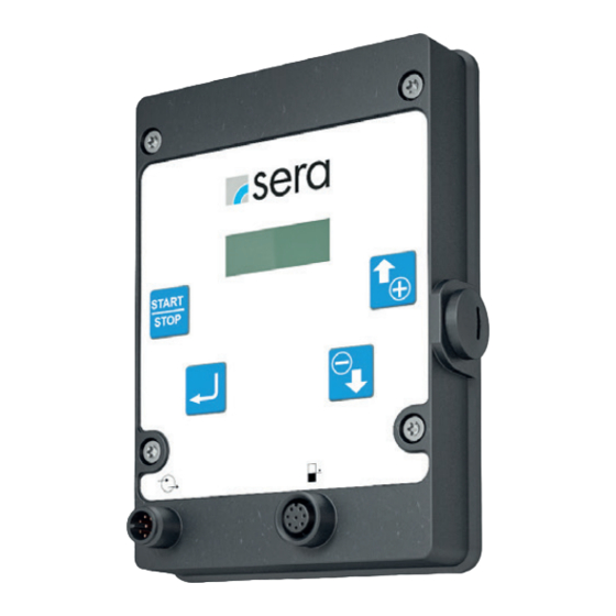
- Page 1 OPERATING MANUAL CONTROL Pro TRANSLATION OF ORIGINAL OPERATING MANUAL...
- Page 2 ATTENTION Technical details subject to change! Quality considerations The sera quality management and quality assurance system is certified according to DIN EN ISO 9001:2015. The sera product complies with the applicable safety requirements and accident prevention regulations. About this manual Special instructions in this manual are marked with text and symbols.
-
Page 3: Table Of Contents
Factory settings ............................... 22 Messages ................................22 Settings (parameters) ............................... 23 TROUBLESHOOTING / FAULT CLEARANCE ................24 MAINTENANCE / DECOMMISSIONING / DISPOSAL ..............26 Maintenance and cleaning ............................26 Decommissioning ..............................26 Disposal .................................. 26 SOFTWARE UPDATE ......................... 27 www.sera-web.com... -
Page 4: Transport & Storage
Man, machine and environment are endangered if the safety instructions are not observed. General sera products are checked for faultless condition and function before shipment. The product must be checked for transport damage immediately after receipt. Any discovered damage must be reported imme- diately to the responsible carrier and the supplier. -
Page 5: Technical Data
Max. line resistance ► Contact signal circuit 100K Ω Sampling rate 1 ms AMBIENT CONDITIONS Max. relative humidity TEMPERATURE INFORMATION Max. operating temperature 40 °C Min. operating temperature 0 °C Max. storage temperature 40 °C Min. storage temperature 0 °C www.sera-web.com... -
Page 6: Electrical Interfaces
Man, machine and environment are endangered if the safety instructions are not observed. Electrical interfaces The controller has 2 interfaces: Interface Assignment Function External control 8-pole Control inputs / control outputs Level connection 8-pole Pre-alarm and dry running protection. www.sera-web.com... - Page 7 Pin 2 (green) Input 3 Analogue Pin 3 (yellow) 24 V external 24 V external Pin 4 (grey) Output 1 Ready to run Pin 5 (pink) Output 2 Stroke signal Pin 6 (blue) Pin 7 (red) Ground Ground Pin 8 www.sera-web.com...
- Page 8 Connection of a pulse signal with External Stop (external control voltage / PLC): Programmable Logic Control (PLC) Pulse 24V DC (output) External Stop 24V DC (output) mA Signal (+) mA output Ready to run Input Stroke signal Input 0V (Ground) www.sera-web.com...
- Page 9 Pre-alarm and dry running are set to normally open floating contacts at the factory. The sockets of the connections are A-coded and the assignations of the functions are symbolically labelled. Assignment Pre-alarm level Dry run Contact signal Contact signal www.sera-web.com...
- Page 10 ELECTRICAL CONNECTIONS Suction lances connection In order to connect the pump to a sera suction lance, an 8-pole ca- ble connector with M12 thread is needed (accessory part number: 90042494 (1) or 90022885) (2)). This cable connector is connected to the level input of the control- ler.
-
Page 11: Operation
Delivery rate (1) START/STOP ENTER DOWN Back Start/Stop Select Confirm warning Suction mode - venting (pump active) Change menu or value Change menu or value Restart pump tap briefly tap and hold for 1 s tap and hold for 3 s www.sera-web.com... -
Page 12: Led Operation Indicators
Diaphragm rupture Analogue operation mA signal < 3.5 mA mA signal > 20.5 mA Service Order service kit / pump active flashing flashing Order service kit / pump not active Stroke (manual acknowledgement) Step loss flashing flashing No stroke detection www.sera-web.com... - Page 13 OPERATION Menu Pulse Parameters Pulse Manual Input 1 Pulse Inputs and outputs Input 2 Analogue Output 1 Output 2 Pre-alarm Dry run www.sera-web.com...
-
Page 14: Assignment
OPERATION Manual Pulse Slow Mode Suction stroke speed Analogue Diaphragm monitoring Input signal Sensitivity Calibration Flow rate indicator Stroke frequency Number of strokes Start calibration System Password Replacement of the diaphragm Service Factory setting www.sera-web.com... -
Page 15: Manual Operating Mode
Message Error messages Warning messages Analogue Delete messages Info Firmware ID Firmware Revision Bootloader ID Serial number sera Code Stroke counter Diaphragm hours Diaphragm process hours Process hours Operating mode Temperature Max. flow rate Analogue Measured value of the Input signal... -
Page 16: Operating Modes
Therefore, it must be strictly ensured that the 24 V output connection is not directly connected to other connections. ATTENTION To avoid damaging the pump, perform parametrisation of the inputs and outputs before connecting the control cable. www.sera-web.com... -
Page 17: Analogue Operating Mode
< 4 mA. Thus, a wire break (control current = 0 mA) can be detected. If the input signal is > 20.5 mA, the pump stops and 4-20m A the error code for the analogue signal > 20 mA is output. Current [mA] www.sera-web.com... -
Page 18: Input 1 (Digital)
■ Signal for operational readiness of the pump. Ready to run Stroke signal ■ Message when a stroke is executed. Contact Output 2 NO / NC contact - Configuration of the contact type (NO or NC contact). Stroke signal www.sera-web.com... -
Page 19: Pre-Alarm, Dry Run
OPERATION Pre-alarm, dry run Pre-alarm The connection of a sera suction lance enables the monitoring of the fill level of the dosing tank: Settings can be made for the following items: Pre-alarm ■ Dry run Dry run ■ Configuration of the two level inputs. You can choose between switching off (OFF) the input or configuring the input as NORMALLY CLOSED (= floating opening NO) or NORMALLY OPEN (= floating closing NC). -
Page 20: Diaphragm Monitoring
Input of the determined delivered quantity (measured value). ■ Standard flow rate indicator With the standard flow rate indicator, the entered target value is converted into the corresponding stroke frequency. Internal calculation: 100% stroke frequency > calibrated: 10l/h Setpoint: 8 l/h > 80% stroke frequency www.sera-web.com... -
Page 21: System
The pump can continue to be operated after the warning message has been acknowl- Operating Manual edged. of the pump NOTE Pre-alarm level If the warning message is acknowledged without replacement, the warning mes- sage repeats after 24 hours. www.sera-web.com... -
Page 22: Factory Settings
However, this is only possible if the signal is no longer present. For example, if the fault has not been rectified, it is not possible to delete the error and it is written to the memory again. Error message Messages Delete messages Pump switches off. Rectify fault. Warning message Messages Delete messages Eliminate cause. www.sera-web.com... -
Page 23: Settings (Parameters)
Stroke signal Contact A2 Normally open contact Pre-alarm NO contact Dry run NO contact Password PW mode Password 0000 Slow mode (stepper motor pump) Suction stroke 100% Diaphragm monitoring Input signal Normally open contact Sensitivity Calibration Active Strokes Speed www.sera-web.com... -
Page 24: Troubleshooting / Fault Clearance
TROUBLESHOOTING / FAULT CLEARANCE sera products are sophisticated technical products which are only shipped after having been thoroughly tested and checked at our factory. Nevertheless, if faults occur, they can be detected and rectified easily and quickly based on the error messages in the display and the instructions in the tables. - Page 25 Possible cause Corrective action Diaphragm has exceeded the maximum service life of one year or the maximum operating Contact sera and order diaphragm kit. █ hours. Pre-alarm level of the storage tank has been Fill storage tank with pumped medium.
-
Page 26: Maintenance / Decommissioning / Disposal
The control unit is maintenance-free. Clean with a moist cloth. Rub dry afterwards. Decommissioning Disconnect device from the power supply. ■ Detach electrical connections. ■ Take device out of operation. ■ Disposal Dispose of correctly and comply with the currently applicable local regulations after shutdown and dismantling. www.sera-web.com... -
Page 27: Software Update
The pump is now in the update mode. Confirm the instructions with the ENTER button. ■ The update is completed. ■ The pump restarts automatically. ■ Disconnect USB-M12 adapter from the pump. ■ The pump is operational. ■ NOTE The parameter settings made on the pump are retained after the software update. www.sera-web.com... - Page 28 FOLLOW US sera GmbH sera-Str. 1 D-34376 Immenhausen Germany Tel. +49 (0) 5673 999 00 +49 (0) 5673 999-01 info@sera-web.com www.sera-web.com...
Need help?
Do you have a question about the CONTROL Pro and is the answer not in the manual?
Questions and answers