
Subscribe to Our Youtube Channel
Related Manuals for S-TEC Fifty Five X


Summary of Contents for S-TEC Fifty Five X
- Page 1 S-TEC Pilot’s Operating Handbook Cirrus SR20/22 Aircraft SR20: SN 1337 and Above SR22: SN 0435 and Above...
- Page 2 S–TEC * Asterisk indicates pages changed, added, or deleted by List of Effective Pages current revision. Page No. Issue Ed, 1 3-18 Ed, 1 Ed, 1 Retain this record in front of handbook. Upon receipt of a Record of Revisions revision, insert changes and complete table below.
- Page 3 S–TEC Page Intentionally Blank 2nd Ed. Nov 15, 07...
-
Page 4: Table Of Contents
S–TEC Table of Contents Sec. Overview......................1–1 Document Organization..............1–3 Purpose....................1–3 General Control Theory..............1–3 Modes of Operation................1–4 1.4.1 Roll Axis Control..............1–4 1.4.2 Pitch Axis Control...............1–4 Block Diagram..................1–4 Pre-Flight Procedures...................2–1 Power-Up Test..................2–3 Pre-Flight Test..................2–7 In-Flight Procedures..................3–1 Normal Operating Procedures............3–3 3.1.1 Heading (HDG) Mode............3–3 3.1.2 Navigation (NAV) Mode............3–4 3.1.2.1 Pilot Selectable Intercept Angle......3–7... - Page 5 S–TEC 3.1.6 Altitude Pre-Select Function..........3–14 3.1.7 Autotrim (SR22 Only)............3–16 3.1.8 Manual Electric Trim (SR22 Only)........3–16 Precision Approach Procedures.............3–18 3.2.1 Straight-In ILS Approach............3–18 3.2.2 ILS Approach with Procedure Turn........3–22 Non-Precision Approach Procedures..........3–22 3.3.1 Straight-In Back Course Approach........3–22 3.3.2 Back Course Approach with Procedure Turn....3–24 3.3.3 Straight-In LOC Approach..........3–26 3.3.4...
- Page 6 S–TEC List of Figures Fig. 1–1 System Fifty Five X Block Diagram..............1–5 2–1 AP Display, Power-Up Annunciations............2–4 2–2 AP Display, Software Revision Number.............2–4 2–3 PFD Display, INITIAL AHRS ALIGNMENT Message.........2–4 2–4 AP Display, RDY Annunciation..............2–5 2–5 PFD Display, AP RDY Annunciation............2–5 2–6...
- Page 7 S–TEC 3–9 PFD Display, HDG Mode Engaged, NAV Mode Armed......3–8 3–10 AP Display, GPSS Mode Engaged..............3–8 3–11 PFD Display, GPSS Mode Engaged............3–9 3–12 AP Display, HDG Mode Engaged, GPSS Mode Armed......3–10 3–13 PFD Display, HDG Mode Engaged, GPSS Mode Armed......3–10 3–14 AP Display, HDG and ALT HOLD Modes Engaged.........3–11 3–15 PFD Display, HDG and ALT HOLD Modes Engaged.......3–11 3–16 AP Display, HDG and VS Modes Engaged..........3–13...
- Page 8 S–TEC 3–33 ....3–24 AP Display, APR Mode Engaged, Track LOC Back Course Outbound 3–34 ....3–24 AP Display, APR Mode Engaged, Track LOC Back Course Inbound 3–35 Back Course Approach with Procedure Turn..........3–25 3–36 ....3–26 AP Display, APR Mode Engaged, Track LOC Front Course Inbound 3–37 Straight-In LOC Approach................3–26 3–38 ....3–27...
- Page 9 S–TEC List of Tables Table 2–1 Power-Up Test....................2–3 2–2 Pre-Flight Test....................2–7 viii 2nd Ed. Nov 15, 07...
-
Page 10: Overview
S–TEC SECTION 1 OVERVIEW 2nd Ed. Nov 15, 07... - Page 11 S–TEC Page Intentionally Blank 2nd Ed. Nov 15, 07...
-
Page 12: Document Organization
Flight Rules (IFR). 1.3 General Control Theory The System Fifty Five X is a rate based autopilot. When in control of the roll axis, the autopilot senses turn rate, as well as closure rate to the selected course, along with the non-rate quantities of heading error, course error, and course deviation indication. -
Page 13: Modes Of Operation
Glideslope (GS) Mode Used to Intercept and Track Glideslope Note: Glidepath can herein this document be used interchangeably with Glideslope. 1.5 Block Diagram The System Fifty Five X Block Diagram is shown in Fig. 1-1. 2nd Ed. Nov 15, 07... -
Page 14: System Fifty Five X Block Diagram
S–TEC Fig. 1-1. System Fifty Five X Block Diagram 2nd Ed. Nov 15, 07... - Page 15 S–TEC Page Intentionally Blank 2nd Ed. Nov 15, 07...
-
Page 16: Pre-Flight Procedures
S–TEC SECTION 2 PRE-FLIGHT PROCEDURES 2nd Ed. Nov 15, 07... - Page 17 S–TEC Page Intentionally Blank 2nd Ed. Nov 15, 07...
-
Page 18: Power-Up Test
S–TEC 2.1 Power-Up Test Perform the actions shown in Table 2-1. For each action, verify the corresponding response where applicable. Table 2-1. Power-Up Test ACTION RESPONSE 1. Set Battery Master Switch to ON All annunciations appear on AP position. display as shown in Fig. 2-1, and then extinguish. -
Page 19: Ap Display, Power-Up Annunciations
S–TEC Fig. 2-1. AP Display, Power-Up Annunciations Fig. 2-2. AP Display, Software Revision Number Fig. 2-3. PFD Display, INITIAL AHRS ALIGNMENT Message 2nd Ed. Nov 15, 07... -
Page 20: Ap Display, Rdy Annunciation
S–TEC Fig. 2-4. AP Display, RDY Annunciation Fig. 2-5. PFD Display, AP RDY Annunciation 2nd Ed. Nov 15, 07... -
Page 21: Ap Display, Fail Annunciation
S–TEC Fig. 2-6. AP Display, FAIL Annunciation Fig. 2-7. PFD Display, AP FAIL Annunciation 2nd Ed. Nov 15, 07... -
Page 22: Pre-Flight Test
S–TEC 2.2 Pre-Flight Test Prior to takeoff and with engine running, perform the actions shown in Table 2-2. For each action, verify the corresponding response where applicable. All actions pertaining to mode selector switches apply to the autopilot, and not the PFD. Table 2-2. -
Page 23: Ap Display, Hdg Mode Engaged (Pre-Flight)
S–TEC Fig. 2-8. AP Display, HDG Mode Engaged (Pre-Flight) Fig. 2-9. PFD Display, HDG Mode Engaged (Pre-Flight) 2nd Ed. Nov 15, 07... -
Page 24: Ap Display, Hdg And Alt Hold Modes Engaged (Pre-Flight)
S–TEC Fig. 2-10. AP Display, HDG and ALT HOLD Modes Engaged (Pre-Flight) Fig. 2-11. PFD Display, HDG and ALT HOLD Modes Engaged (Pre-Flight) 2nd Ed. Nov 15, 07... - Page 25 S–TEC Table 2-2. Pre-Flight Test (continued from page 2-7) ACTION RESPONSE 9. Attempt movement of A/C Control Control Sidestick’s reduced Sidestick forward and aft (A/C with freedom of movement indicates that Pitch Servo Only). Pitch Servo is engaged. Pitch Servo can be overridden. If not, disconnect autopilot and do not use.
-
Page 26: Ap Display, Hdg And Vs Modes Engaged (Pre-Flight)
S–TEC Fig. 2-12. AP Display, HDG and VS Modes Engaged (Pre-Flight) Fig. 2-13. PFD Display, HDG and VS Modes Engaged (Pre-Flight) 2nd Ed. Nov 15, 07 2-11... - Page 27 S–TEC Table 2-2. Pre-Flight Test (continued from page 2-10) ACTION RESPONSE 18. Set PFD Alt Bug to higher A/C Control Sidestick moves in aft altitude, then engage direction. Altitude Pre-Select Function simultaneously pressing VS and ALT ALT and VS annunciations appear on mode selector switches.
- Page 28 S–TEC Table 2-2. Pre-Flight Test (continued from page 2-12) ACTION RESPONSE 24. Rotate Modifier Knob ½ turn CW. FD Steering Command Bars on PFD slowly move to a pitch up position. 25. Rotate Modifier Knob 1 turn FD Steering Command Bars on PFD CCW.
- Page 29 S–TEC Table 2-2. Pre-Flight Test (continued from page 2-13) ACTION RESPONSE 33. Press AP DISC / TRIM INTR annunciation flashes Switch, to disconnect autopilot. audible alert sounds a periodic tone, while all other annunciations are Note: extinguished. Pressing and holding AP DISC / After 5 seconds, RDY annunciation TRIM INTR Switch will limit audible stops flashing but remains, and...
-
Page 30: In-Flight Procedures
S–TEC SECTION 3 IN-FLIGHT PROCEDURES 2nd Ed. Nov 15, 07... - Page 31 S–TEC Page Intentionally Blank 2nd Ed. Nov 15, 07...
-
Page 32: Normal Operating Procedures
S–TEC 3.1 Normal Operating Procedures 3.1.1 Heading (HDG) Mode Set the PFD Hdg Bug to the desired heading on the compass card, and press the HDG mode selector switch to engage the heading mode. HDG annunciation will appear as shown in Fig. 3-1. The autopilot will turn the aircraft onto the selected heading and hold it. -
Page 33: Navigation (Nav) Mode
S–TEC 3.1.2 Navigation (NAV) Mode Select a VOR frequency on the Navigation Receiver. Set the PFD CRS Pointer to the desired course on the compass card, and press the NAV mode selector switch to engage the navigation mode. The NAV annunciation will appear as shown in Fig. -
Page 34: Pfd Display, Nav Mode Engaged, A/C Turning Onto Course
S–TEC As the aircraft approaches the selected course, the autopilot will sense the corresponding rate at which the Left/Right Needle approaches center (closure rate), and gradually shallow the intercept angle as the autopilot turns the aircraft onto the course. A typical view of the PFD during this stage of the intercept sequence is shown in Fig. -
Page 35: Pfd Display, Nav Mode Engaged, A/C Tracking Course
S–TEC Thirty seconds after course capture, the autopilot will establish the required crosswind correction angle. Seventy five seconds after course capture, a third step reduction in autopilot gain occurs to limit the aircraft's turn rate to 15% of a standard rate turn. In addition, the sensitivity to closure rate is reduced once more. -
Page 36: Pilot Selectable Intercept Angle
S–TEC The NAV annunciation will flash whenever the CDI needle deflection exceeds 50%, or the NAV Flag is in view. In the latter event, the FAIL annunciation will also appear. While tracking in the LOW GAIN condition and within 50% CDI needle deflection, to track in the higher authority INTERMEDIATE GAIN condition, press the APR mode selector switch to engage the approach mode. -
Page 37: Global Positioning System Steering (Gpss) Mode
S–TEC Fig. 3-9. PFD Display, HDG Mode Engaged, NAV Mode Armed 3.1.3 Global Positioning System Steering (GPSS) Mode The GPSS mode should be used anytime the selected navigation source is the Global Positioning System (GPS). Engagement of the GPSS mode requires pressing the NAV mode selector switch twice, unless the NAV mode is engaged. - Page 38 S–TEC The autopilot will laterally steer the aircraft along a predefined course programmed into the Navigation Receiver, and limit its turn rate to either: 130% of a standard rate turn (Prog/Comp Hardware Mod Code AM and below) 90% of a standard rate turn (Prog/Comp Hardware Mod Code AN and AP) 110% of a standard rate turn (Prog/Comp Hardware Mod Code AR and above) During the GPSS mode of operation, the autopilot will not accept any course error input from the PFD CRS Pointer.
-
Page 39: Pilot Selectable Intercept Angle
S–TEC 3.1.3.1 Pilot Selectable Intercept Angle To select a course intercept angle, set the PFD Hdg Bug to the desired intercept heading on the compass card, such that the difference between this heading and the next course segment is the intercept angle. Press and hold the HDG mode selector switch, and press the NAV mode selector switch twice to engage the HDG mode and arm the GPSS mode. -
Page 40: Altitude Hold (Alt) Mode
S–TEC 3.1.4 Altitude Hold (ALT) Mode The altitude hold mode can only be engaged if a roll mode (HDG, NAV, APR, GPSS, REV) is engaged. With a roll mode engaged and the aircraft at the desired altitude, press the ALT mode selector switch to engage the altitude hold mode. -
Page 41: Vertical Speed (Vs) Mode
S–TEC 3.1.5 Vertical Speed (VS) Mode Caution: The vertical speed mode may be used for establishing and maintaining a PILOT selected vertical speed. The autopilot receives no airspeed information; therefore, it is the responsibility of the pilot to manage the vertical speed selection within the operating limits of the aircraft's capabilities. -
Page 42: Ap Display, Hdg And Vs Modes Engaged
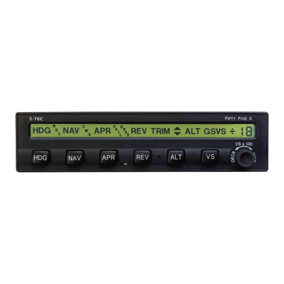
S–TEC Fig. 3-16. AP Display, HDG and VS Modes Engaged Fig. 3-17. PFD Display, HDG and VS Modes Engaged Fig. 3-18. AP Display, HDG and VS Modes Engaged, PFD Failure 2nd Ed. Nov 15, 07 3-13... -
Page 43: Altitude Pre-Select Function
S–TEC 3.1.6 Altitude Pre-Select Function The Altitude Pre-Select Function allows the pilot to pre-select a target altitude and the vertical speed (if within the aircraft's capabilities) at which the aircraft will climb or descend, until that altitude is captured. Engage a roll mode (HDG, NAV, APR, GPSS, REV). Set the PFD Alt Bug to the target altitude and the PFD VSI Bug to an acceptable vertical speed. -
Page 44: Ap Display, Hdg And Vs Modes Engaged, Alt Hold Mode Armed
S–TEC Fig. 3-19. AP Display, HDG and VS Modes Engaged, ALT HOLD Mode Armed Fig. 3-20. PFD Display, HDG and VS Modes Engaged, ALT HOLD Mode Armed Fig. 3-21. AP Display, HDG and ALT HOLD Modes Engaged 2nd Ed. Nov 15, 07 3-15... -
Page 45: Autotrim (Sr22 Only)
S–TEC 3.1.7 Autotrim (A/C with Pitch Servo Only) When the Remote AP ON Switch has been selected (reference section 3.4.1), and both a roll mode (HDG, NAV, APR, REV, GPSS) and a pitch mode (ALT, VS, GS) are engaged, the autopilot will provide an annunciation whenever it is automatically trimming the aircraft. - Page 46 S–TEC Page Intentionally Blank 2nd Ed. Nov 15, 07 3-17...
-
Page 47: Precision Approach Procedures
S–TEC 3.2 Precision Approach Procedures 3.2.1 Straight-In ILS Approach Execute a straight-in intercept and track of the FRONT INBOUND LOC course (reference section 3.3.3), while holding the approach altitude. The NAV, APR, and ALT annunciations will appear as shown in Fig. 3-23. A typical view of the PFD during this stage of the ILS approach sequence is shown in Fig. -
Page 48: Ap Display, Nav, Apr, And Alt Hold Modes Engaged
S–TEC The GS annunciation will flash whenever the Glideslope Deviation Indication (GDI) needle deflection exceeds 50%, or the GS Flag is in view. In the latter event, the FAIL annunciation will also appear. At the Decision Height (DH) or Missed Approach Point (MAP), disconnect the autopilot to execute either a manual landing or go-around, respectively. -
Page 49: Ap Display, Nav, Apr And Alt Hold Modes Engaged, Gs Mode Armed
S–TEC Fig. 3-25. AP Display, NAV, APR and ALT HOLD Modes Engaged, GS Mode Armed Fig. 3-26. PFD Display, NAV, APR, and ALT HOLD Modes Engaged, GS Mode Armed 3-20 2nd Ed. Nov 15, 07... -
Page 50: Straight-In Ils Approach
S–TEC Fig. 3-27. AP Display, NAV, APR, and GS Modes Engaged Fig. 3-28. PFD Display, NAV, APR, and GS Modes Engaged Fig. 3-29. Straight-In ILS Approach 2nd Ed. Nov 15, 07 3-21... -
Page 51: Ils Approach With Procedure Turn
S–TEC 3.2.2 ILS Approach with Procedure Turn Execute a procedure turn intercept and track of the FRONT INBOUND LOC course (reference section 3.3.5) above the approach altitude, just until the aircraft is established on the FRONT INBOUND PROCEDURE TURN heading, with the HDG mode still engaged. Set the PFD VSI Bug to the desired vertical descent speed, and press the VS mode selector switch to engage the VS mode. -
Page 52: Straight-In Back Course Approach
S–TEC Fig. 3-31. AP Display, APR Mode Engaged, Back Course Back Course 265° 085° 310° a. Select LOC frequency. b. Set PFD CRS Pointer to FRONT INBOUND LOC course. c. Press REV mode selector switch to engage APR mode. d. Intercept and track BACK INBOUND LOC course. Fig. -
Page 53: Back Course Approach With Procedure Turn
S–TEC 3.3.2 Back Course Approach with Procedure Turn Select the LOC frequency on the Navigation Receiver. Set the PFD CRS Pointer to the FRONT INBOUND LOC course on the compass card. Press the NAV mode selector switch to engage the APR mode. NAV and APR annunciations will appear as shown in Fig. -
Page 54: Back Course Approach With Procedure Turn
S–TEC Back Course 085° 265° 310° 130° 1. a. Select LOC frequency. b. Set PFD CRS Pointer to FRONT INBOUND LOC course. c. Press NAV mode selector switch to engage APR mode. d. Intercept and track BACK OUTBOUND LOC course. 2. -
Page 55: Straight-In Loc Approach
S–TEC 3.3.3 Straight-In LOC Approach Select the LOC frequency on the Navigation Receiver. Set the PFD CRS Pointer to the FRONT INBOUND LOC course on the compass card. Press the NAV mode selector switch to engage the APR mode. NAV and APR annunciations will appear as shown in Fig. -
Page 56: Straight-In Vor Approach
S–TEC 3.3.4 Straight-In VOR Approach Select the VOR frequency on the Navigation Receiver. Set the PFD CRS Pointer to the FRONT INBOUND VOR course on the compass card. Press the APR mode selector switch to engage the APR mode. NAV and APR annunciations will appear as shown in Fig. -
Page 57: Loc Approach With Procedure Turn
S–TEC 3.3.5 LOC Approach with Procedure Turn Select the LOC frequency on the Navigation Receiver. Set the PFD CRS Pointer to the FRONT INBOUND LOC course on the compass card. Press the REV mode selector switch to engage the APR mode. REV and APR annunciations will appear as shown in Fig. -
Page 58: Loc Approach With Procedure Turn
S–TEC 130° 310° 1. a. Select LOC frequency. b. Set PFD CRS Pointer to FRONT INBOUND LOC course. c. Press REV mode selector switch to engage APR mode. d. Intercept and track FRONT OUTBOUND LOC course. 2. a. At the appropriate time, set PFD Hdg Bug to FRONT OUTBOUND PROCEDURE TURN heading. -
Page 59: Vor Approach With Procedure Turn
S–TEC 3.3.6 VOR Approach with Procedure Turn Select the VOR frequency on the Navigation Receiver. Set the PFD CRS Pointer to the FRONT INBOUND VOR course on the compass card. Press the REV mode selector switch to engage the REV mode. The REV annunciation will appear as shown in Fig. -
Page 60: Vor Approach With Procedure Turn
S–TEC 130° 310° 1. a. Select VOR frequency. b. Set PFD CRS Pointer to FRONT INBOUND VOR course. c. Press REV mode selector switch to engage REV mode. d. Intercept and track FRONT OUTBOUND VOR course. 2. a. At the appropriate time, set PFD Hdg Bug to FRONT OUTBOUND PROCEDURE TURN heading. -
Page 61: Gpss Approach (Lateral Guidance Only)
S–TEC 3.3.7 GPSS Approach (Lateral Guidance Only) Press the NAV mode selector switch twice to engage the GPSS mode (reference section 3.1.3). The autopilot will laterally steer the aircraft along a predefined approach, which has been programmed into the Navigation Receiver. To control the assigned altitudes and rates of descent, use the Altitude Pre-Select Function (reference section 3.1.6). -
Page 62: Fd Mode
S–TEC 3.4.2 FD Mode Press the Remote AP OFF / FD ON Switch, and engage a roll and pitch mode to enable the FD mode. In this case, the Steering Command Bars are green. The pilot must steer the aircraft toward the Steering Command Bars, until the ARS is tucked into them. -
Page 63: Waas Procedures
S–TEC 3.5 WAAS Procedures 3.5.1 GPS Approach (With Vertical Guidance) For 400W/500W Series equipped aircraft, when conducting a WAAS approach, if the GPSS mode remains engaged, then the autopilot will execute the entire lateral procedure automatically (i.e., intercept and track front outbound course, complete procedure turn, intercept and track front inbound course). -
Page 64: Operating Parameters
S–TEC SECTION 4 OPERATING PARAMETERS 2nd Ed. Nov 15, 07... - Page 65 S–TEC Page Intentionally Blank 2nd Ed. Nov 15, 07...
-
Page 66: Roll Axis Limits
S–TEC 4.1 Roll Axis Limits Turn Rate 90% Standard Rate Turn (HDG, NAV, APR, REV Modes) 130% Standard Rate Turn (GPSS Mode) for Programmer/Computers with Hardware Mod Code AM and below. 90% Standard Rate Turn (GPSS Mode) for Programmer/Computers with Hardware Mod Code AN and AP. - Page 67 S–TEC Page Intentionally Blank 2nd Ed. Nov 15, 07...
-
Page 68: Glossary
S–TEC SECTION 5 GLOSSARY 2nd Ed. Nov 15, 07... - Page 69 S–TEC Page Intentionally Blank 2nd Ed. Nov 15, 07...
- Page 70 S–TEC Term Meaning Aircraft AHRS Attitude and Heading Reference System Altitude Autopilot Approach Aircraft Reference Symbol Airspeed Indication Course Deviation Indication Clockwise Counter–Clockwise Course Decision Height DISC Disconnect Federal Aviation Administration Final Approach Fix Flight Director Feet–per–Minute Feet Glideslope Deviation Indication Global Positioning System GPSS Global Positioning System Steering...
- Page 71 S–TEC Page Intentionally Blank 2nd Ed. Nov 15, 07...
- Page 72 Information contained in this document is subject to change without notice. © 2008 S-TEC. All rights reserved. Printed in the United States of America. S-TEC and the S-TEC logo are registered trademarks of S-TEC. Notice: Contact S-TEC Customer Support at 800-872-7832 for a Return Material Authorization (RMA) number prior to the return of any component for any reason.
Need help?
Do you have a question about the Fifty Five X and is the answer not in the manual?
Questions and answers