
Related Manuals for S-TEC Fifty Five X

Summary of Contents for S-TEC Fifty Five X
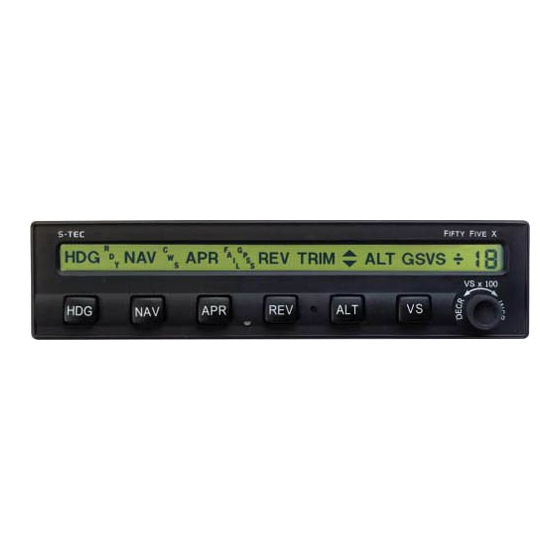
- Page 1 IFTY IVE REV TRIM ALT GS VS VS x 100...
- Page 2 S–TEC * Asterisk indicates pages changed, added, or deleted by List of Effective Pages current revision. Page No. Issue * 3-7 Apr 15, 07 3-11 Mar 15, 07 * 4-3 Apr 15, 07 Retain this record in front of handbook. Upon receipt of a Record of Revisions revision, insert changes and complete table below.
- Page 3 S–TEC Page Intentionally Blank 3rd Ed. Sep 30, 06...
-
Page 4: Table Of Contents
S–TEC Table of Contents Sec. Overview......................1–1 Document Organization..............1–3 Purpose....................1–3 General Control Theory..............1–3 Modes of Operation................1–4 1.4.1 Roll Axis Control..............1–4 1.4.2 Pitch Axis Control...............1–4 Block Diagram..................1–4 Pre-Flight Procedures...................2–1 Power-Up Test..................2–3 Pre-Flight Test..................2–6 In-Flight Procedures..................3–1 Normal Operating Procedures............3–3 3.1.1 Heading (HDG) Mode............3–3 3.1.2 Navigation (NAV) Mode............3–3 3.1.2.1 Pilot Selectable Intercept Angle......3–6... - Page 5 S–TEC Precision Approach Procedures.............3–12 3.2.1 Straight-In ILS Approach............3–12 3.2.1.1 Software Revision 5 and Above......3–12 3.2.1.2 Software Revision 4 and Below......3–14 3.2.2 ILS Approach with Procedure Turn........3–15 Non-Precision Approach Procedures..........3–15 3.3.1 Straight-In Back Course Approach........3–15 3.3.1.1 Pilot Selectable Intercept Angle.......3–17 3.3.2 Back Course Approach with Procedure Turn....3–18 3.3.3 Straight-In LOC Approach..........3–21...
- Page 6 S–TEC List of Figures Fig. 1–1 System Fifty Five X Block Diagram..............1–5 2–1 AP Display, All Annunciations at Power-Up..........2–4 2–2 AP Display, Software Revision Number.............2–4 2–3 AP Display, Ready for Operation..............2–4 2–4 AP Display, Programmer/Computer Failure..........2–5 2–5 AP Display, Turn Coordinator Failure............2–5 2–6...
- Page 7 S–TEC 3–11 AP Display, HDG and ALT HOLD Modes Engaged........3–8 3–12 AP Display, HDG and VS Modes Engaged..........3–9 3–13 AP Display, CWS Mode Engaged..............3–9 3–14 AP Display, Manual Trim Prompts............3–14 3–15 AP Display, Automatic Trim Advisements..........3–11 3–16 AP Display, Manual Electric Trim in Progress..........3–12 3–17 AP Display, NAV APR and ALT HOLD Modes Engaged......3–13 3–18 ....3–13...
- Page 8 S–TEC 3–38 AP Master Switch, FD/AP Mode Engaged..........3–31 3–39 FD Display, FD/AP Mode Engaged............3–32 3–40 AP Master Switch, FD Mode Engaged............3–32 3–41 Remote Annunciator Display, FD Mode Engaged........3–32 3–42 FD Display, FD Mode Engaged..............3–33 3–43 Yaw Damper Master Switch................3–33 3–44 Yaw Damper Trim Knob................3–33 List of Tables Table 2–1...
- Page 9 S–TEC Page Intentionally Blank viii 3rd Ed. Sep 30, 06...
-
Page 10: Overview
S–TEC SECTION 1 OVERVIEW 3rd Ed. Sep 30, 06... - Page 11 S–TEC Page Intentionally Blank 3rd Ed. Sep 30, 06...
-
Page 12: Document Organization
Conditions (VMC), prior to using it under Instrument Flight Rules (IFR). 1.3 General Control Theory The System Fifty Five X is a rate based autopilot. When in control of the roll axis, the autopilot senses turn rate, as well as closure rate to the selected course, along with the non-rate quantities of heading error, course error, and course deviation indication. -
Page 13: Modes Of Operation
Used to Hold Altitude Vertical Speed (VS) Mode Used to Hold Vertical Speed Glideslope (GS) Mode Used to Intercept and Track Glideslope 1.5 Block Diagram The System Fifty Five X Block Diagram is shown in Fig. 1-1. 3rd Ed. Sep 30, 06... -
Page 14: System Fifty Five X Block Diagram
S–TEC Fig. 1-1. System Fifty Five X Block Diagram 3rd Ed. Sep 30, 06... - Page 15 S–TEC Page Intentionally Blank 3rd Ed. Sep 30, 06...
-
Page 16: Pre-Flight Procedures
S–TEC SECTION 2 PRE-FLIGHT PROCEDURES 3rd Ed. Sep 30, 06... - Page 17 S–TEC Page Intentionally Blank 3rd Ed. Sep 30, 06...
-
Page 18: Power-Up Test
S–TEC 2.1 Power-Up Test Perform the actions shown in Table 2-1. For each action, verify the corresponding response where applicable. Table 2-1. Power-Up Test ACTION RESPONSE 1. Set Yaw Damper Master Switch ------ to OFF position (if installed). 2. Set Trim Master Switch to OFF ------ position (if installed). -
Page 19: Ap Display, All Annunciations At Power-Up
S–TEC Fig. 2-1. AP Display, All Annunciations at Power-Up Fig. 2-2. AP Display, Software Revision Number Fig. 2-3. AP Display, Ready for Operation 3rd Ed. Sep 30, 06... -
Page 20: Ap Display, Programmer/Computer Failure
S–TEC Fig. 2-4. AP Display, Programmer/Computer Failure Fig. 2-5. AP Display, Turn Coordinator Failure 3rd Ed. Sep 30, 06... -
Page 21: Pre-Flight Test
S–TEC 2.2 Pre-Flight Test Prior to takeoff and with engine running, perform the actions shown in Table 2-2. For each action, verify the corresponding response where applicable. All actions pertaining to mode selector switches apply to the autopilot bezel. Table 2-2. Pre-Flight Test (continued on page 2-8) ACTION RESPONSE 1. -
Page 22: Ap Display, Hdg Mode Engaged (Pre-Flight)
S–TEC Fig. 2-6. AP Display, HDG Mode Engaged (Pre-Flight) Fig. 2-7. AP Display, HDG and ALT HOLD Modes Engaged (Pre-Flight) 3rd Ed. Sep 30, 06... - Page 23 S–TEC Table 2-2. Pre-Flight Test (continued from page 2-6) ACTION RESPONSE ±1) 11. Press/Hold CWS Switch to arm CWS, control wheel steering mode. annunciations only appear on AP display, as shown in Fig. 2-8. 12. Move A/C Control Wheel left and Control Wheel’s increased...
-
Page 24: Ap Display, Cws Mode Armed Or Engaged, 0 Fpm (Pre-Flight)
S–TEC Fig. 2-8. AP Display, CWS Mode Armed or Engaged, 0 FPM (Pre-Flight) Fig. 2-9. AP Display, CWS Mode Engaged, 500 FPM Climbing (Pre-Flight) Fig. 2-10. AP Display, CWS Mode Engaged, 500 FPM Descending (Pre-Flight) 3rd Ed. Sep 30, 06... - Page 25 S–TEC Table 2-2. Pre-Flight Test (continued from page 2-8) ACTION RESPONSE 20. Select local VOR frequency on ------ Navigation Receiver. Note: Proceed to either step 21 (HSI) or step 26 (DG). 21. Turn Course Pointer until CDI ------ needle is centered. 22.
-
Page 26: Ap Display, Nav And Vs Modes Engaged, 0 Fpm (Pre-Flight)
S–TEC Fig. 2-11. AP Display, NAV and VS Modes Engaged, 0 FPM (Pre-Flight) 3rd Ed. Sep 30, 06 2-11... - Page 27 S–TEC Table 2-2. Pre-Flight Test (continued from page 2-10) ACTION RESPONSE 29. Turn OBS until CDI needle is A/C Control Wheel stops. centered. 30. Press HDG mode selector switch HDG, VS, and +0 annunciations only to engage heading mode. appear on AP display. ∧...
-
Page 28: Ap Display, Manual Trim Prompts (Pre-Flight)
S–TEC a. HDG and VS Modes Engaged, 0 FPM, TRIM UP Required b. HDG and VS Modes Engaged, 0 FPM, TRIM DN Required Fig. 2-12. AP Display, Manual Trim Prompts (Pre-Flight) 3rd Ed. Sep 30, 06 2-13... - Page 29 S–TEC Table 2-2. Pre-Flight Test (continued from page 2-12) ACTION RESPONSE ∧ 35. Move A/C Control Wheel as far After seconds, TRIM forward as possible. annunciation appears on AP display as shown in Fig. 2-13a, and Elevator Trim Wheel begins to run nose up with increasing speed.
-
Page 30: Ap Display, Automatic Trim Advisements (Pre-Flight)
S–TEC a. HDG and VS Modes Engaged, 0 FPM, TRIM UP in Progress b. HDG and VS Modes Engaged, 0 FPM, TRIM DN in Progress Fig. 2-13. AP Display, Automatic Trim Advisements (Pre-Flight) Fig. 2-14. Remote Annunciator Display, HDG, VS, and FD Modes Engaged (Pre-Flight) 3rd Ed. - Page 31 S–TEC Table 2-2. Pre-Flight Test (continued from page 2-14) ACTION RESPONSE Note: If autopilot is equipped with autotrim, then proceed to step 41. Otherwise, proceed to step 42. 41. Move A/C Control Wheel as far After 3 seconds, Elevator Trim Wheel forward or aft as possible.
- Page 32 S–TEC Table 2-2. Pre-Flight Test (continued from page 2-16) ACTION RESPONSE 49. Move A/C Control Wheel as far After 3 seconds, Elevator Trim Wheel forward or aft as possible. begins to run, indicating that Trim Servo is engaged. 50. Press either forward or aft on Autopilot disconnects as follows: both segments of Manual Electric Trim Switch.
-
Page 33: Ap Display, Manual Electric Trim In Progress (Pre-Flight)
S–TEC Fig. 2-15. AP Display, Manual Electric Trim in Progress (Pre-Flight) 2-18 3rd Ed. Sep 30, 06... - Page 34 S–TEC Table 2-2. Pre-Flight Test (continued from page 2-17) ACTION RESPONSE 57. Press/Hold AP DISC / TRIM Elevator Trim Wheel stops. INTR Switch. 58. Release AP DISC / TRIM INTR Elevator Trim Wheel resumes running Switch. nose up at full speed. 59.
- Page 35 S–TEC Table 2-2. Pre-Flight Test (continued from page 2-19) ACTION RESPONSE 64. Attempt actuation of A/C Rudder A/C Rudder Pedals’ reduced freedom Pedals alternately in succession. of movement indicates that Yaw Servo is engaged. Yaw Servo can be overridden. If not, set Yaw Damper Master Switch to OFF position, and do not use.
-
Page 36: In-Flight Procedures
S–TEC SECTION 3 IN-FLIGHT PROCEDURES 3rd Ed. Sep 30, 06... - Page 37 S–TEC Page Intentionally Blank 3rd Ed. Sep 30, 06...
-
Page 38: Normal Operating Procedures
S–TEC 3.1 Normal Operating Procedures 3.1.1 Heading (HDG) Mode Set the Heading Bug to the desired heading on the compass card (HSI or DG), and then press the HDG mode selector switch to engage the heading mode. The HDG annunciation will appear as shown in Fig. 3-1, to acknowledge that this mode is engaged. - Page 39 S–TEC If the Course Deviation Indication (CDI) is at full scale (100%) needle deflection from center, then the autopilot will establish the aircraft on a 45° intercept angle relative to the selected course. Even if CDI needle deflection is less than 100%, the autopilot may still establish an intercept angle of 45°, provided that the aircraft's closure rate to the selected course is sufficiently slow.
-
Page 40: Remote Annunciator Display, Nav Mode Engaged, Cap Condition
S–TEC While tracking in the SOFT condition, the autopilot ignores short term CDI needle deflections (excursions), to thereby inhibit aircraft scalloping during VOR station passage. Should CDI needle deflection exceed 50% for a period of 60 seconds, the autopilot will revert to the CAP SOFT condition as a means to re-establish the aircraft on course. -
Page 41: Pilot Selectable Intercept Angle
S–TEC Fig. 3-6. AP Display, NAV APR Mode Engaged Fig. 3-7. Remote Annunciator Display, NAV APR Mode Engaged, CAP SOFT Condition 3.1.2.1 Pilot Selectable Intercept Angle To select an intercept angle other than 45°, set the Heading Bug to the desired intercept heading on the compass card, such that the difference between this heading and the desired course is the intercept angle. -
Page 42: Pilot Selectable Intercept Angle
S–TEC 3.1.3 Navigation Global Positioning System Steering (NAV GPSS) Mode Program a predefined course into the GPS Navigation Receiver, comprised of course segments connected by waypoints. Press the NAV mode selector switch twice to engage the navigation global positioning system steering mode, unless the navigation mode is already engaged. -
Page 43: Altitude Hold (Alt Hold) Mode
S–TEC 3.1.4 Altitude Hold (ALT HOLD) Mode The altitude hold mode can only be engaged if a roll mode (HDG, NAV, NAV APR, REV, REV APR, NAV GPSS) is already engaged. With a roll mode engaged and the aircraft at the desired altitude, press the ALT mode selector switch to engage the altitude hold mode. -
Page 44: Control Wheel Steering (Cws) Mode
S–TEC Fig. 3-12. AP Display, HDG and VS Modes Engaged 3.1.6 Control Wheel Steering (CWS) Mode The control wheel steering mode can only be engaged if a roll mode (HDG, NAV, NAV APR, REV, REV APR, NAV GPSS) and pitch mode (ALT, VS, GS) are already engaged. -
Page 45: Automatic Elevator Trim
S–TEC Should the pitch servo loading exceed a preset threshold for a period of three ∧ ∨ seconds, the autopilot will annunciate either Trim or Trim as a prompt to trim the aircraft in the indicated direction. This is shown in Fig. 3-14. In addition, an audible alert will sound a periodic tone. -
Page 46: Manual Electric Elevator Trim
S–TEC a. TRIM UP in Progress b. TRIM DN in Progress Fig. 3-15. AP Display, Automatic Trim Advisements 3.1.7.3 Manual Electric Elevator Trim If the autopilot is equipped with autotrim, then there will also be the remote Manual Electric Trim Switch located on the Control Wheel. This switch can be used to trim the aircraft about the pitch axis from the RDY, or when only a roll mode (HDG, NAV, NAV APR, REV, REV APR, NAV GPSS) is engaged, provided that the Trim Master Switch is in the ON position. -
Page 47: Precision Approach Procedures
S–TEC Fig. 3-16. AP Display, Manual Electric Trim in Progress 3.2 Precision Approach Procedures 3.2.1 Straight-In ILS Approach 3.2.1.1 Software Revision 5 and Above Execute a straight-in intercept and track of the FRONT INBOUND LOC course (reference section 3.3.3), while holding the approach altitude. The NAV, APR, and ALT annunciations will appear as shown in Fig. -
Page 48: Ap Display, Nav Apr And Alt Hold Modes Engaged
S–TEC Note: If the approach positions the aircraft slightly above the GS centerline, then manual engagement of the glideslope mode can be instantly achieved by pressing the ALT mode selector switch. Caution: Manual engagement of the glideslope mode above the GS centerline will result in the aircraft moving aggressively toward the GS centerline. -
Page 49: Software Revision 4 And Below
S–TEC Fig. 3-20. Straight-In ILS Approach 3.2.1.2 Software Revision 4 and Below Execute a straight-in intercept and track of the FRONT INBOUND LOC course (reference section 3.3.3), while holding the approach altitude. The NAV, APR, and ALT annunciations will appear as shown in Fig. 3-17. Once the following conditions have existed simultaneously for a period of ten seconds, the GS annunciation will appear to acknowledge that the glideslope mode has automatically armed, as shown in Fig. -
Page 50: Ils Approach With Procedure Turn
S–TEC Note: If the approach positions the aircraft slightly above the GS centerline, then manual engagement of the glideslope mode can be instantly achieved by pressing the ALT mode selector switch. Caution: Manual engagement of the glideslope mode above the GS centerline will result in the aircraft moving aggressively toward the GS centerline. -
Page 51: Ap Display, Rev Apr Mode Engaged, Track Loc Back Course Inbound
S–TEC The REV annunciation will flash whenever CDI needle deflection exceeds 50%, or the NAV Flag is in view. In the latter event, the FAIL annunciation will also appear. A summary pictorial of this procedure is shown in Fig. 3-22. Fig. -
Page 52: Pilot Selectable Intercept Angle
S–TEC 3.3.1.1 Pilot Selectable Intercept Angle To select an intercept angle, set the Heading Bug to the desired intercept heading on the compass card, such that the difference between this heading and the BACK INBOUND LOC course is the intercept angle. If the heading system is an HSI, set the Course Pointer to the FRONT INBOUND LOC course on the compass card. -
Page 53: Back Course Approach With Procedure Turn
S–TEC 3.3.2 Back Course Approach with Procedure Turn Select the LOC frequency on the Navigation Receiver. Heading System HSI Set Course Pointer to FRONT INBOUND LOC course on compass card. Heading System DG Set Heading Bug to FRONT INBOUND LOC course on compass card. Press the NAV mode selector switch to engage the navigation approach mode. -
Page 54: Ap Display, Rev Apr Mode Engaged, Track Loc Back Course Inbound
S–TEC At the appropriate time, set the Heading Bug to the BACK OUTBOUND PROCEDURE TURN heading, and then press the HDG mode selector switch to engage the heading mode. Hold this heading until the point at which it is time to turn the aircraft again. -
Page 55: Back Course Approach With Procedure Turn
S–TEC Back Course 085° 265° 310° 130° 1. a. Select LOC frequency. b. Heading System HSI Set Course Pointer to FRONT INBOUND LOC course. Heading System DG Set Heading Bug to FRONT INBOUND LOC course. c. Press NAV mode selector switch to engage navigation approach mode. d. -
Page 56: Straight-In Loc Approach
S–TEC 3.3.3 Straight-In LOC Approach Select the LOC frequency on the Navigation Receiver. Heading System HSI Set Course Pointer to FRONT INBOUND LOC course on compass card. Heading System DG Set Heading Bug to FRONT INBOUND LOC course on compass card. Press the NAV mode selector switch to engage the navigation approach mode. -
Page 57: Straight-In Loc Approach
S–TEC 1. a. Select LOC frequency. b. Heading System HSI Set Course Pointer to FRONT INBOUND LOC course. Heading System DG Set Heading Bug to FRONT INBOUND LOC course. c. Press NAV mode selector switch to engage navigation approach mode. d. -
Page 58: Straight-In Vor Approach
S–TEC 3.3.4 Straight-In VOR Approach Select the VOR frequency on the Navigation Receiver. Heading System HSI Set Course Pointer to FRONT INBOUND VOR course on compass card. Heading System DG Set Heading Bug and OBS to FRONT INBOUND VOR course on each respective compass card. -
Page 59: Straight-In Vor Approach
S–TEC 1. a. Select VOR frequency. b. Heading System HSI Set Course Pointer to FRONT INBOUND VOR course. Heading System DG Set Heading Bug and OBS to FRONT INBOUND VOR course. c. Press APR mode selector switch to engage navigation approach mode. d. -
Page 60: Loc Approach With Procedure Turn
S–TEC 3.3.5 LOC Approach with Procedure Turn Select the LOC frequency on the Navigation Receiver. Heading System HSI Set Course Pointer to FRONT INBOUND LOC course on compass card. Heading System DG Set Heading Bug to BACK INBOUND LOC course on compass card. Press the REV mode selector switch to engage the reverse approach mode. -
Page 61: Ap Display, Nav Apr Mode Engaged, Track Loc Front Course Inbound
S–TEC At the appropriate time, set the Heading Bug to the FRONT OUTBOUND PROCEDURE TURN heading, and then press the HDG mode selector switch to engage the heading mode. Hold this heading until the point at which it is time to turn the aircraft again. -
Page 62: Loc Approach With Procedure Turn
S–TEC 130° 310° 1. a. Select LOC frequency. b. Heading System HSI Set Course Pointer to FRONT INBOUND LOC course. Heading System DG Set Heading Bug to BACK INBOUND LOC course. c. Press REV mode selector switch to engage reverse approach mode. d. -
Page 63: Vor Approach With Procedure Turn
S–TEC 3.3.6 VOR Approach with Procedure Turn Select the VOR frequency on the Navigation Receiver. Heading System HSI Set Course Pointer to FRONT INBOUND VOR course on compass card. Heading System DG Set Heading Bug and OBS to BACK INBOUND VOR course on each respective compass card. -
Page 64: Ap Display, Nav Apr Mode Engaged, Track Vor Front Course Inbound
S–TEC At the appropriate time, set the Heading Bug to the FRONT OUTBOUND PROCEDURE TURN heading, and then press the HDG mode selector switch to engage the heading mode. Hold this heading until the point at which it is time to turn the aircraft again. -
Page 65: Vor Approach With Procedure Turn
S–TEC 130° 310° 1. a. Select VOR frequency. b. Heading System HSI Set Course Pointer to FRONT INBOUND VOR course. Heading System DG Set Heading Bug and OBS to BACK INBOUND VOR course. c. Press REV mode selector switch to engage reverse mode. d. -
Page 66: Nav Gpss Approach
S–TEC 3.3.7 NAV GPSS Approach Program a predefined approach into the GPS Navigation Receiver. Press the NAV mode selector switch twice to engage the navigation global positioning system steering mode (reference section 3.1.3). The autopilot will laterally steer the aircraft along the predefined approach. To control the assigned altitudes and rates of descent, use the altitude hold mode (reference section 3.1.4) and vertical speed mode (reference section 3.1.5), respectively. -
Page 67: Fd Mode
S–TEC Fig. 3-39. FD Display, FD/AP Mode Engaged 3.4.2 FD Mode With the Autopilot Master Switch in the FD/AP position, together with a roll mode (HDG, NAV, NAV APR, REV, REV APR, NAV GPSS) and pitch mode (ALT, VS, GS) engaged, set the Autopilot Master Switch to the FD position as shown in Fig. -
Page 68: Yaw Damper Operation
S–TEC Fig. 3-42. FD Display, FD Mode Engaged 3.5 Yaw Damper Operation The optional Yaw Damper serves to dampen excessive adverse yaw. It operates in either the AUTO mode or ON mode, depending upon the position of the Yaw Damper Master Switch shown in Fig. 3-43. AUTO Fig. -
Page 69: Auto Mode
S–TEC 3.5.1 AUTO Mode With the Yaw Damper Master Switch in the AUTO position, the yaw servo will become automatically engaged whenever a roll mode (HDG, NAV, NAV APR, REV, REV APR, NAV GPSS) is engaged. 3.5.2 ON Mode With the Yaw Damper Master Switch in the ON position, the yaw servo will be engaged at all times, entirely independent of autopilot operation. -
Page 70: Operating Parameters
S–TEC SECTION 4 OPERATING PARAMETERS 3rd Ed. Sep 30, 06... - Page 71 S–TEC Page Intentionally Blank 3rd Ed. Sep 30, 06...
-
Page 72: Roll Axis Limits
S–TEC 4.1 Roll Axis Limits Turn Rate Piston A/C: 90% Standard Rate Turn (HDG, NAV, NAV APR, REV, REV APR, CWS Modes) Turboprop A/C: 75% Standard Rate Turn (HDG, NAV, NAV APR, REV, REV APR, CWS Modes) All A/C: 130% Standard Rate Turn (NAV GPSS Mode) for Programmer/Computers with Hardware Mod Code AM and below. - Page 73 S–TEC Page Intentionally Blank 3rd Ed. Sep 30, 06...
-
Page 74: Glossary
S–TEC SECTION 5 GLOSSARY 3rd Ed. Sep 30, 06... - Page 75 S–TEC Page Intentionally Blank 3rd Ed. Sep 30, 06...
- Page 76 S–TEC Term Meaning Aircraft Adjustment Altitude Autopilot Approach Aircraft Reference Symbol Capture Course Deviation Indication Clockwise Control Wheel Steering Counter–Clockwise Course Directional Gyro Decision Height DISC Disconnect Federal Aviation Administration Flight Director Feet–per–Minute Feet Go Around Glideslope Deviation Indication Global Positioning System GPSS Global Positioning System Steering Glideslope...
- Page 77 S–TEC Page Intentionally Blank 3rd Ed. Sep 30, 06...
- Page 78 Information contained in this document is subject to change without notice. © 2007 S-TEC. All rights reserved. Printed in the United States of America. S-TEC and the S-TEC logo are registered trademarks of S-TEC. Notice: Contact S-TEC Customer Support at 800-872-7832 for a Return Material Authorization (RMA) number prior to the return of any component for any reason.
Need help?
Do you have a question about the Fifty Five X and is the answer not in the manual?
Questions and answers