Table of Contents
Advertisement
Advertisement
Table of Contents

Related Manuals for S-TEC Meggitt System 55X


Summary of Contents for S-TEC Meggitt System 55X
- Page 1 System Fifty Five X Autopilot Pilot’s Operating Handbook...
- Page 2 SYS FIFTY FIVE X POH * Asterisk indicates pages changed, added, or deleted by List of Effective Pages revision. Retain this record in front of handbook. Upon receipt of a Record of Revisions revision, insert changes and complete table below. Edition Number Publication Date Insertion Date/Initials...
-
Page 3: Table Of Contents
SYS FIFTY FIVE X POH TABLE OF CONTENTS Section Page Editons........................i Table of Contents....................iii List of Figures.......................v Introduction......................1-3 System Fifty Five X Block Diagram..............2-3 Autopilot Overview....................3-3 Procedures......................4-3 Pre-flight Procedures................4-3 4.1.1 Autopilot Self Test..............4-3 4.1.2 Pre-flight Test................4-4 4.1.3 Manual Electric Trim Test............4-6 Normal Operating Procedures............4-7 4.2.1 Heading Mode.................4-7... -
Page 4: Table Of Contents
SYS FIFTY FIVE X POH TABLE OF CONTENTS (Cont'd) Section Page Approach Procedures.................4-19 4.3.1 Procedure Turn Localizer Approach (Standard DG)..4-19 4.3.2 Straight-In Localizer Intercept & Tracking (Standard DG)................4-21 4.3.3 Pilot Selectable Intercept Angles (Standard DG)...4-22 4.3.4 Procedure Turn Localizer Approach (Optional HSI)..4-22 4.3.5 Localizer Intercept &... -
Page 5: List Of Figures
SYS FIFTY FIVE X POH LIST OF FIGURES FIGURE Page 4.3.3.1 Procedure Turn Localizer Approach & Track (Standard DG)..................4-20 4.3.4.1 Procedure Turn Localizer Approach & Tracking (Opt HSI)....4-24 4.3.5.1 Straight-In Localizer Approach & Tracking (Opt HSI)....4-26 4.3.7.1 Glide-slope Intercept & Track.............4-28 4.3.7.2 Procedure Turn for Glide-slope Approach........4-29 4.3.9.1... -
Page 6: Introduction
SYS FIFTY FIVE X POH SECTION 1 INTRODUCTION 2nd Ed: May 31, 2002... - Page 7 SYS FIFTY FIVE X POH Introduction The primary purpose of the System Fifty Five X Pilot Operating Handbook (POH) is to provide pilots with step-by-step functional Preflight and In- Flight Operating Procedures for the installed system. This System Fifty Five X Pilot's Operating Handbook, part number 87109, dated 31 May 2002 or later, must be carried in the aircraft and be made available to the pilot while in flight.
- Page 8 SYS FIFTY FIVE X POH SECTION 2 BLOCK DIAGRAM 1st Ed: May 31, 2002...
-
Page 9: System Fifty Five X Block Diagram
SYS FIFTY FIVE X POH Block Diagram SYSTE M FIFTY FIV E X BLOC K DIA GR A M R EMO TE A NN U NC IATO R F LIG H T D IR ECTO R A UTO PILO T D ISCO NN EC T/ (O PTIO N A L) (O PTIO N A L) T RIM IN TER RU PT SW IT C H... -
Page 10: Autopilot Overview
SYS FIFTY FIVE X POH SECTION 3 AUTOPILOT OVERVIEW 2nd Ed: May 31, 2002... - Page 11 SYS FIFTY FIVE X POH 3.0 Autopilot Overview 3.1 System Fifty Five X Autopilot Overview The System Fifty Five X is a rate autopilot that controls the roll and pitch axes of the aircraft. The autopilot's main function is to convert pilot commands to logic signals for the roll and pitch computers.
-
Page 12: Procedures
SYS FIFTY FIVE X POH SECTION 4 PROCEDURES 2nd Ed: May 31, 2002... -
Page 13: Pre-Flight Procedures
SYS FIFTY FIVE X POH Procedures Pre-Flight Procedures 4.1.1 Autopilot Self-Test NOTE: The System Fifty Five X incorporates a SELF-TEST that requires a 100% pass rate before the autopilot can be engaged. To perform the test, aircraft DC electrical power must be supplied to the autopilot. 1. -
Page 14: Pre-Flight Test
SYS FIFTY FIVE X POH 4.1.2 Pre-flight Test 1. Trim Master (ON / OFF) Switch..............ON 2. HDG and VS switches............PRESS / RELEASE —Ensure that HDG and VS illuminates on the Fifty Five X annunciator. 3. Control Wheel Steering (CWS) switch......PRESS / RELEASE —Verify that CWS and VS are highlighted on the annunciator. - Page 15 SYS FIFTY FIVE X POH 12. Trim Master (ON / OFF) Switch..............OFF NOTE: If HSI equipped, center the course arrow under the lubber line and push the NAV button. Move the course arrow on the HSI left then right. Roll control should follow the course arrow.
-
Page 16: Manual Electric Trim Test
SYS FIFTY FIVE X POH 4.1.3 Manual Electric Trim Test 1. Trim Master (ON / OFF) switch..............ON —Move each segment of the Manual Electric Trim Command Switch FWD and AFT. Trim should not run. —Move both segments of the Trim Command switch FWD. Trim should run nose down. -
Page 17: Normal Operating Procedures
4.2.2 NAV Intercept and Tracking If your aircraft is equipped with an HSI, your S-TEC autopilot will receive both left / right deviation and course information. With an HSI, the heading bug is not used during tracking. To intercept and track a VOR or GPS course, select the desired course with the HSI Course Pointer and engage the NAV Mode. - Page 18 SYS FIFTY FIVE X POH During the intercept sequence, the system operates in maxium gain and sensitivity to needle position and motion and can command the aircraft at 90% of the standard rate turn. When the selected course is intercepted, and the needle is centered, indicating course capture, initiation of the tracking gain program is automatic.
-
Page 19: Pilot Selectable Intercept Angles (Dg Or Hsi)
SYS FIFTY FIVE X POH When operating in the NAV / SOFT Mode and a needle deflection of 50% or more is experienced for 1.5 minutes, the gain program will switch to NAV/CAP/SOFT, increasing sensitivity and authority to reestablish the aircraft on course. -
Page 20: Approach (Apr) Mode Switch
SYS FIFTY FIVE X POH 4.2.3 Approach (APR) Mode Switch The APR Mode provides increased sensitivity for VOR or GPS approaches. The pilot may also select this mode if increased sensitivity is desired for enroute NAV tracking. To engage this mode press the APR switch on the Programmer / Computer. -
Page 21: Gpss Operating Procedures
SYS FIFTY FIVE X POH 4.2.5 GPSS Operating Procedures 1. To enter the GPSS Mode, push the NAV button twice. 2. The autopilot will accept steering commands from the GPS unit and will fly the lateral segments of the approach without any further input from the pilot. -
Page 22: Standard Gps Approach
SYS FIFTY FIVE X POH NOTE: Some Fifty Five X Autopilot installations inhibit the use of the GPSS mode when the NAV source selector switch on the GPS navigator is in the VOR / LOC position or the external NAV selector switch (as appropriate) is in NAV position. -
Page 23: Gps Steering (Gpss) Approach
SYS FIFTY FIVE X POH 3. Select the APR Mode. The autopilot will intercept and track the GPS signal. 4. If desired, the pilot can use the pilot selectable intercept angle procedure as described on preceeding pages. (Ref. 4.2.5.1 Pilot Selectable Intercept Angles). -
Page 24: Altitude (Alt)
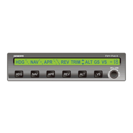
SYS FIFTY FIVE X POH The + (positive) symbol annunciation indicates a veritcal speed climb selection. Clockwise rotation of the VS knob increases the rate of climb and counter-clockwise rotation decreases the rate of climb to 0. The (negative) symbol annuncation indicates a vertical speed descent selection. -
Page 25: Control Wheel Steering (Cws)
SYS FIFTY FIVE X POH 4.2.11 Control Wheel Steering The System Fifty Five X Autopilot is equipped with a Control Wheel steering (CWS) Mode of operation that is entered by use of the CWS switch located on the control wheel. In order to use the mode, both a roll and pitch axis mode must be engaged. -
Page 26: Pitch Trim Indicator
SYS FIFTY FIVE X POH 4.2.12 Pitch Trim Indicator If automatic trim has failed or is turned off, a sensor in the System Fifty Five X Autopilot pitch servo detects out-of-trim elevator loads. When such forces exceed a preset level and time delay, TRIM will annunciate on the Programmer / Computer with either the up or down symbol annunciated to indicate the direction elevator trim is required. - Page 27 AFT for nose up. TRIM will be annunciated and will flash while the trim is in motion. NOTE: The S-TEC trim system is designed to accept any type of single failure (mechanical or electrical) without uncontrolled operation resulting. To ensure that no hidden failures have occurred, conduct a trim pre-flight check prior to every flight.
-
Page 28: Approach Procedures
SYS FIFTY FIVE X POH Approach Procedures 4.3.1 Procedure Turn Localizer Approach (Standard DG) Select the appropriate localizer frequency. Set the heading bug to the OUTBOUND localizer course and engage the REV Mode to track the localizer front course outbound or back course inbound. When a localizer is channeled and REV Mode is selected, the System Fifty Five X will automatically execute high sensitivity gain for the approach and APR and REV will be annunciated. - Page 29 SYS FIFTY FIVE X POH If the heading bug is within 5 of center and needle deflection is less than10%, the computer will immediately establish this sensitivity level when REV is selected. Set the heading bug to the outbound procedure turn heading and select heading mode.
- Page 30 SYS FIFTY FIVE X POH 4.3.2 Straight-In Localizer Intercept and Tracking (Standard DG) With the appropriate localizer frequency selected, set the heading bug to the INBOUND localizer course and engage the NAV mode to track the localizer front course inbound or back course outbound. When a localizer is channeled and NAV Mode is selected, the System Fifty Five X will automatically execute high sensitivity gain for the approach and activate the APR Mode.
-
Page 31: Pilot Selectable Intercept Angles (Standard Dg)
SYS FIFTY FIVE X POH 4.3.3 Pilot Selectable Intercept Angles (Standard DG) The pilot may select an angle of intercept less than the standard 45 Place the heading bug on the DG to the desired heading used for the course intercept and simultaneously push both HDG and NAV switches. HDG, NAV, and APR will be displayed on the autopilot annunciator. - Page 32 SYS FIFTY FIVE X POH During the intercept sequence, the system operates at maximum gain and sensitivity to needle position and motion and can command the aircraft at 90% of the standard rate turn. When the localizer course is intercepted and the needle is centered (indicating course capture), initiation of the tracking gain program is automatic.
- Page 33 SYS FIFTY FIVE X POH 4.3.4.1 Procedure Turn Localizer Approach and Tracking with Optional HSI 1. a. Tune navigation radio to LOC frequency. b. Set published inbound LOC course heading with course pointer. c. Push REV Mode switch. 2. a. Set heading bug to published outbound procedure turn heading.
- Page 34 SYS FIFTY FIVE X POH 4.3.5 Straight-In Localizer Intercept and Tracking (Optional HSI) With the appropriate localizer frequency selected, set the course selector to the INBOUND localizer course and engage the NAV Mode to track the localizer front course inbound or back course outbound. When a localizer is channeled and NAV Mode is selected, the system will automatically execute high sensitivity gain for the approach and activate the APR Mode with NAV and APR being annunciated.
-
Page 35: Pilot Selectable Intercept Angles (Optional Hsi)
SYS FIFTY FIVE X POH If the course selector is within 5 ! of center and needle deflection is less than 10%, the computer will immediately establish this sensitivity level when NAV is selected. Since the heading bug is not used for the final approach segment, the pilot may elect to move the heading bug to the published missed approach heading for reference and use in the heading mode should a missed approach be necessary. -
Page 36: Glide-Slope Intercept & Tracking
SYS FIFTY FIVE X POH The selected heading will now be flown until the autopilot computes that an on course turn must be made to minimize overshoot at the point of intercept. At the time the on course turn begins, the HDG Mode will extinguish. - Page 37 SYS FIFTY FIVE X POH NOTE: If vectored to intercept the localizer too close to the glide- slope intercept point (resulting in less than 60% GS needle deviation when on course), the system will not automatically arm the glide-slope. Manual arming must be followed.
- Page 38 SYS FIFTY FIVE X POH 4.3.7.2 Procedure Turn for Glide-slope Approach 1. a. Tune navigation radio to ILS frequency. b. Follow the procedure(s) for LOC Approach Intercept and Tracking in this manual. 2. a. If a procedure turn is required, enter the procedure turn above the published altitude.
-
Page 39: Manual Arm / Automatic Capture
SYS FIFTY FIVE X POH 4.3.8 Manual Arm / Automatic Capture If approach vectoring locates the aircraft above or too near the glideslope centerline at the intercept point (usually the outer marker), it becomes necessary to execute manual arming of the glideslope. This is done by pressing the ALT switch once (if operating in the altitude hold mode) pressing the ALT switch twice (if operating in the VS Mode). -
Page 40: Procedure Turn Localizer Back-Course Approach (Optional Hsi)
SYS FIFTY FIVE X POH CAUTION If the aircraft is not equipped with the optional remote annunciator, the only indication that the glide-slope function has been disabled is the flashing GS annunciator on the autopilot programmer. To fly the holding pattern, if inbound to the Outer Marker, press the APR switch twice to disable the glide-slope arming. - Page 41 SYS FIFTY FIVE X POH During the intercept sequence, the system operates in maximum gain and sensitivity to needle positon and motion and can command the aircraft at 90% of the standard rate turn. When the localizer course i s intercepted and the needle is centered (indicating course capture), initiation of the tracking gain program is automatic.
- Page 42 SYS FIFTY FIVE X POH 4.3.9.1 Back-Course Procedure Turn (HSI) REVerse Mode is used to track the front course outbound or the back course inbound to the airport. The HSI Course Pointer MUST be set to the front course inbound heading.
-
Page 43: Localizer Back Course Intercept And Tracking (Optional Hsi)
SYS FIFTY FIVE X POH 4.3.10 Localizer Back-Course Intercept and Tracking (Optional HSI) With the appropriate localizer frequency selected, set the course pointer to the INBOUND Localizer FRONT Course and engage the REV Mode to track the localizer back course inbound or front course outbound. When a localizer is channeled and REV Mode is selected, the System Fifty Five X will automatically execute high sensitivity gain for the approach and automatically activate the APR Mode. - Page 44 SYS FIFTY FIVE X POH If the course pointer is within 5 of center and needle deflection is less than 10%, the computer will immediately establish this sensitivity level when REV is selected. Since the heading bug is not used for the final approach segment, the pilot may elect to move the heading bug to the published Missed Approach Heading for reference and use in the Heading Mode, should a Missed Approach be necessary.
- Page 45 SYS FIFTY FIVE X POH 4.3.9.2 Back Course Straight-In Approach (Optional HSI) 1. a. Tune navigation radio to LOC frequency. b. Set Course Pointer to published inbound front course heading. c. Press REV Mode switch. d. Heading bug can be set to missed approach heading after course capture.
-
Page 46: System Failure And Caution Annunciations
SYS FIFTY FIVE X POH System Failure and Caution Annunciations The System Fifty Five X contains a number of automatic failure and caution annunciations to advise the pilot of operational problems. They are the following: ANNUNCIATION CONDITION ACTION Flashing RDY for 5 Indicates autopilot seconds with disconnect. -
Page 47: Autopilot Disconnect
SYS FIFTY FIVE X POH NOTE: If any of the aforementioned failure annunciations occur at low altitude or during an actual instrument approach disengage the autopilot and execute a go-around or missed approach as appropriate. Inform ATC of the problem. Do not attempt to troubleshoot or otherwise identify the nature of the failure until a safe altitude and maneuvering area are reached or safe landing is executed. -
Page 48: Yaw Damper Preflight Procedures
SYS FIFTY FIVE X POH 4.6.2 Yaw Damper Pre-flight Procedures 1. Place the Yaw Damper Master switch in the YAW AUTO position and engage the autopilot HDG Mode. Note that the Yaw Damper engages and causes increased pedal force. 2. Rotate the Yaw Damper Trim Control clockwise and note that the right rudder pedal moves slowly forward. -
Page 49: Single-Cue Flight Director Operation (Optional)
SYS FIFTY FIVE X POH Single-Cue Flight Director Operation (Optional) This system, which integrates both the roll axis and pitch axis, offers synchronized display of the flight profile. It is automatically activated when the autopilot is engaged. A Flight Director provides a visual indication of how accurately the pilot or autopilot is tracking the commands of the active mode of operation. - Page 50 SYS FIFTY FIVE X POH For manually controlled flight by the flight director, place the FD/AP master switch in the "FD" position. This disables the autopilot servos, allowing the pilot to control the aircraft to the flight director commands. To engage the autopilot without interruption, simply place the FD/AP master switch in the "FD/AP"...
- Page 51 SYS FIFTY FIVE X POH SECTION 5 SPECIFICATIONS 2nd Ed: May 31, 2002...
- Page 52 SYS FIFTY FIVE X POH Appendix A: Specifications System Requirements Programmer/Computer Power required 14/28 VDC Weight 3.0 lbs. Dimensions 6.25 X 1.50 X 10.60 in. NOTE: Unit will operate with either 14 or 28 VDC input; however internal circuit board assemblies must be set up for a specific voltage.
- Page 53 SYS FIFTY FIVE X POH SPECIFICATIONS (Cont'd) Altitude Pressure Transducer Power required: 10 VDC (supplied by autopilot) Pressure range: 0-15 PSI absolute Overpressure: 150% of operating maximum Weight: 0.2 lbs. Remote Annunciator (OPTIONAL) Power required: 0.2 Amp (max) Weight: 0.75 lbs. Dimensions: 1.60 X 3.42 X 3.80 in.
-
Page 54: Glossary
SYS FIFTY FIVE X POH SECTION 6 GLOSSARY 2nd Ed: May 31, 2002... - Page 55 SYS FIFTY FIVE X POH GLOSSARY Term Meaning AFMS Airplane Flight Manual Supplement Altitude Approach Air Traffic Control Capture Course Deviation Indicator CON'T Continued Control Wheel Steering Directional Gyro DSBL Disable Federal Aviaton Adminstration Flight Director Feet Per Minute Global Positioning System GPSS Global Positioning System Steering Glideslope...
- Page 56 1-800-USA-STEC www.s-tec.com Information in this document is subject to change without notice. ©2002 S-TEC Corporation. All rights reserved. Printed in the United States of America. S-TEC and the S-TEC logo are registered trademarks of S-TEC Corporation. P/N: 87109 Date: May 31, 2002...
Need help?
Do you have a question about the Meggitt System 55X and is the answer not in the manual?
Questions and answers