Table of Contents
Advertisement
Quick Links
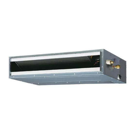
AIR CONDITIONER
INDOOR UNIT
Duct Type
INSTALLATION MANUAL
INSTALLATION MANUAL
For authorized service personnel only.
INSTALLATIONSANLEITUNG
Nur für autorisiertes Personal.
MANUEL D'INSTALLATION
Pour le personnel agréé uniquement.
MANUAL DE INSTALACIÓN
Solo para personal autorizado.
MANUALE D'INSTALLAZIONE
Ad uso esclusivo del personale autorizzato.
ΕΓΧΕΙΡΙΔΙΟ ΕΓΚΑΤΑΣΤΑΣΗΣ
Για εξουσιοδοτημένο προσωπικό σέρβις.
MANUAL DE INSTALAÇÃO
Apenas para técnicos autorizados.
РУКОВОДСТВО ПО УСТАНОВКЕ
Для уполномоченного персонала.
KURULUM KILAVUZU
Yetkili servis personeli içindir.
PART NO. 9374815173-04
Advertisement
Table of Contents

Related Manuals for Fujitsu ARHG12LLTB


Summary of Contents for Fujitsu ARHG12LLTB
- Page 1 AIR CONDITIONER INDOOR UNIT Duct Type INSTALLATION MANUAL INSTALLATION MANUAL For authorized service personnel only. INSTALLATIONSANLEITUNG Nur für autorisiertes Personal. MANUEL D'INSTALLATION Pour le personnel agréé uniquement. MANUAL DE INSTALACIÓN Solo para personal autorizado. MANUALE D'INSTALLAZIONE Ad uso esclusivo del personale autorizzato. ΕΓΧΕΙΡΙΔΙΟ...
-
Page 2: Table Of Contents
INSTALLATION MANUAL This mark indicates procedures which, if improperly performed, CAUTION! might possibly result in personal harm to the user, or damage to PART NO. 9374815173-04 property. INDOOR UNIT (Duct Type) Read carefully all security information before use or install the air conditioner. Contents Do not attempt to install the air conditioner or a part of the air conditioner by yourself. SAFETY PRECAUTIONS ..................1 This unit must be installed by qualified personnel with a capacity certificate for handling ABOUT THE UNIT... -
Page 3: Accessories
2.3. Accessories Name and Shape Q’ty Application Hose band For installing drain hose WARNING • For installation purposes, be sure to use the parts supplied by the manufacturer or other prescribed parts. The use of non-prescribed parts can cause serious accidents such as the unit to fall, water leakage, electric shock, or fire. -
Page 4: Installation Dimensions (Ceiling Concealed Type)
CAUTION 3.2B. Installation dimensions (Wall mounted type/Floor standing concealed type) • If children under 10 years old may approach the unit, take preventive measures so that they cannot reach the unit. The wall mounted type/floor standing concealed type requires a temperature • Decide the mounting position with the customer as follows: correction setting. Perform this in “7.3. Function setting ”. (1) Install the indoor unit in a location having sufficient strength to support the weight of the indoor unit. 10 mm 10 mm or less or less (2) The inlet and outlet ports should not be obstructed; the air should be able to blow all Right side (PIPE side) - Page 5 Replace the cover as follows. Inlet side • Remove the screws, and then remove cover and fan guard. • Install the cover with the screws as shown in the illustration below. Screw Model 7000,9000,12000,14000 BTU/h 18000 BTU/h screw (M5) Cover 7000,9000,12000,14000 BTU/h 18000 BTU/h 650 mm 850 mm P200×2=400 mm P200×3=600 mm CAUTION Fan guard • Be sure to install the air inlet grille and the air outlet grille for air circulation. The correct temperature cannot be detected.
-
Page 6: Install The Unit (Wall Mounted Type/ Floor Standing Concealed Type)
3.3A.4. FIX THE UNIT 3.3B. Install the unit (Wall mounted type/ Floor standing concealed type) (1) Hang the unit Hanger Hanger bolt WARNING • Install the air conditioner in a location which can withstand a load do at least 5 Nut A times the weight of the main unit and which will not amplify sound or vibration. If the (Field supply) installation location is not strong enough, the indoor unit may fall and cause injuries. -
Page 7: Pipe Installation
3.3B.2. INSTALL THE FILTER • Install the filters (Accessories) to the unit. NO GOOD Level Filter Unit Filter Replace drain cap NO GOOD CAUTION • Fasten the unit securely with Special nuts A and B. 4. PIPE INSTALLATION CAUTION • Be careful that foreign matter (oil, water, etc.) does not enter the piping with refrigerant R410A models. Also, when storing the piping, securely seal the openings CAUTION by pinching, taping, etc. • Set “7.4. Jumper wire setting of Drainage function setting (JM1)”. -
Page 8: Pipe Requirement
4.3.3. Pipe connection 4.2. Pipe requirement CAUTION CAUTION • Be sure to install the pipe against the port on the indoor unit correctly. If the centering is improper, the flare nut cannot tighten smoothly. If the flare nut is forced to turn, the • Refer to the Installation Manual of the outdoor unit for description of the length of threads will be damaged. -
Page 9: Installing Drain Pipes
WARNING 5. INSTALLING DRAIN PIPES • Do not insert the drain piping into the sewer where sulfurous gas occurs. (Heat exchange erosion may occur) 5.1A. Installing drain pipes (Ceiling concealed type) • Insulate the parts properly so that water will not drip from the connection parts. Use general hard polyvinyl chloride pipe and connect it with adhesive (polyvinyl chloride) • Check for proper drainage after the construction by using the visible portion of so that there is no leakage. - Page 10 (2) Be sure to insert Drain hose 1 to the very end of the Drain pan of the unit with no space. • STEP1~STEP3 Butt the insulation against the unit. Applying Unit Joint pipe area of (Field supply) adhesive Drain pipe (VP25) (Field supply) Slit 4 mm or less 1 Drain hose 2 Hose band...
-
Page 11: Electrical Wiring
(1) Use ring terminals with insulating sleeves as shown in the figure below to connect to 6. ELECTRICAL WIRING the terminal block. (2) Securely clamp the ring terminals to the cables using an appropriate tool so that the cables do not come loose. Cable Cable size (mm Type Remarks (3) Use the specified cables, connect them securely, and fasten them so that there is no stress placed on the terminals. Connection cable Type 60245 IEC57 3Cable+Ground, 1φ230V (4) Use an appropriate screwdriver to tighten the terminal screws. Max. Cable Length: Limit voltage drop to less than 2%. Increase cable gauge if voltage drop is Do not use a screwdriver that is too small, otherwise, the screw heads may be 2% or more. -
Page 12: Wiring System Diagram
(2) Cable connection 6.1. Wiring system diagram • Connect the connection cable to the terminal board. • Connect the remote controller cable to the terminal board. • Fix the remote controller cable to the control box cover with a nylon clamp. Connection cable to outdoor unit or BRANCH BOX Type 60245 IEC57 OUTDOOR UNIT or INDOOR UNIT Cable size 1.5 mm BRANCH BOX (Inter-unit) TERMINAL Power lines Power line Remote controller cable 1: Red 2: White 3: Black Control line Please connect it to the specified terminal. Grounding line Earth Binder (Medium) Wired remote controller cable (Accessories) -
Page 13: Remote Controller Setting
7. REMOTE CONTROLLER SETTING CAUTION When detecting the room temperature using the remote con- Temperature troller, please set up the remote controller according to the sensor following conditions. If the remote controller is not located prop- erly, the correct room temperature will not be detected, and thus abnormal conditions like “not cooled” or “not heated” will occur even if the air-conditioner is running normally. -
Page 14: Function Setting
• Function Details 7.3. Function setting (1) Filter Sign This procedure changes the function settings used to control the indoor unit according to The indoor unit has a sign to inform the user that it is time to clean the filter. Select the the installation conditions. Incorrect settings can cause the indoor unit to malfunction. This procedure should be performed by authorized installation or service personnel only. time setting for the filter sign display interval in the table below according to the amount of dust or debris in the room. If you do not wish the filter sign to be displayed, select the Perform the “FUNCTION SETTING” according to the installation conditions using the remote... -
Page 15: Jumper Wire Setting
B. Indoor unit/remote controller setting (room tempera- * A uto restart is an emergency function such as for power failure etc. Do not start and stop the indoor unit by this function in normal operation. Be sure to operate by the control unit, ture sensor selection) or external input device. The temperature sensor of the indoor unit or the remote controller can be used to detect (6) Indoor room temperature sensor switching function the room temperature. -
Page 16: Special Installation Methods
8. TEST RUN 7.5. Special installation methods CAUTION CAUTION • A lways turn on the power 12 hours prior to the start of the operation in order to ensure • When setting DIP switches, do not touch any other parts on the circuit board directly compressor protection. with your bare hands. CHECK ITEMS • Be sure to turn off the main power. 7.5.1. Group control system (1) Is operation of each button on the remote controller normal? (2) Does each lamp light normally? CAUTION... -
Page 17: Optional Parts
9. OPTIONAL PARTS 9.3. Remote sensor (Optional parts) Connection method WARNING • Connection terminals • R egulation of cable differs from each locality, refer in accordance with local rules. This air conditioner can be connected with the following optional kits. Refer to each installation manual for the method of installing optional parts. -
Page 18: Auto Louver Grille (Optional Parts)
• Wiring arrangement 9.6. Optional parts cable binding Binder (Medium/Accessories) Binder* Air inlet Bushing** Knockout hole Auto louver grille cable Remote controller cable Other optional parts cables Binders* Bind with this cable. Power supply • Use 7 pins for receiver unit cable. cable Avoid covering the air • At first, connect the receiver unit cable to the Receiver unit terminal (CN13). inlet with the wirings. 9.5. -
Page 19: Error Codes
Liquid pipe temp. sensor error 11. ERROR CODES ● ● ◊ Current sensor error If you use a wired type remote controller, error codes will appear on the remote ● ● ◊ controller display. If you use a wireless remote controller, the lamps on the IR receiver unit will output error codes by way of blinking patterns. See the lamp blinking patterns •...
Need help?
Do you have a question about the ARHG12LLTB and is the answer not in the manual?
Questions and answers