Table of Contents
Advertisement
Quick Links
Advertisement
Table of Contents

Related Manuals for Sonotec SONAPHONE E


Summary of Contents for Sonotec SONAPHONE E
- Page 1 Ultrasonic Testing Device SONAPHONE ® Operating Manual...
- Page 2 The contents of the operating manual are the property of SONOTEC GmbH and protected by copyright. Copying and distribution in any form, especially as reprint, photomechanical or electronic reproduction, or in the form of storage in data processing systems or data networks without the permission of the copyright holder is prohibited.
-
Page 3: Table Of Contents
Arrangement of devices and accessories in the transportation case ............15 Function description ..........16 Designated use ............. 16 General information ............17 SONAPHONE E connections, control- and display elements................ 18 Operation ............... 19 Insert the batteries ............19 Performing the battery change ..........19 Starting up the unit ............ - Page 4 SONAPHONE ® Main menu ..............27 Menu structure ................. 27 Operation .................. 27 Data logger ..............28 General information ..............28 Long-time test ................29 Single test ................. 36 Test parameters ............38 Device reset................38 Setting the averaging time ............38 Setting the tester ..............
- Page 5 SONAPHONE ® PC connection & data transfer ......53 Power supply via USB ........... 59 Cleaning ..............61 Troubleshooting and self-help in case of errors 62 Technical specifications ........63 Warranty ..............64 Operating Manual – Revision: 2.4 | 2020-11-17 Page 5 of 66...
- Page 6 SONAPHONE ® (This page has been deliberately left empty) Operating Manual – Revision: 2.4 | 2020-11-17 Page 6 of 66...
-
Page 7: Information On This Document
SONAPHONE. It must therefore be read prior to first use and before carrying out any further steps. This document has been created with all due care. SONOTEC does not assume any guarantee of the completeness, correctness and current validity of the provided data, and is not liable for errors or omissions. -
Page 8: Symbols Used
SONAPHONE ® Symbols used Hazards or special information are indicated in the following ways: Warns of imminent threat of danger with very high risk. If not avoided, it will result in death or serious injury. Warns of possible imminent danger which, if ignored, may lead to lasting adverse health effects and/or serious material damages. -
Page 9: Safety Precautions
(in full) and understood the safety instructions as well as all further instructions in the operating manual. SONOTEC GmbH accepts no liability for damage, including to third parties, caused by improper handling of the device. Operating Manual – Revision: 2.4 | 2020-11-17... -
Page 10: Instructions On The Operating Conditions Of The Sonaphone
SONAPHONE ® Instructions on the operating conditions of the SONAPHONE E in potentially explosive atmospheres ® Risk of death or severe injury. Incorrect operation, damage to the device as well as damage to accessories can impair the explosion protection. The SONAPHONE E is intended for use in areas where there ®... - Page 11 SONAPHONE ® The SONAPHONE E, the surface temperature sensor and the ® headphones comply with EPL (Equipment protection level) b. SONAPHONE® E II2G Ex ia IIC T4 Gb The ultrasonic probes L60, L61, L62 and L63 comply with EPL (Equipment protection level) b for gas group IIC, IIB and IIA. Ultrasonic probes L60, L61, L62 and L63 II2G Ex ia IIC T4 Gb In addition, the ultrasonic probes L60 and L61 comply with EPL (Equipment...
-
Page 12: General Safety Instructions For Use Of The Sonaphone
– are only permitted to be connected to the SONAPHONE ® if all defined conditions are met. Only those sensors which are offered by SONOTEC ® accessories are permitted to be used as 'additional sensors'. If the ‘additional sensor’ is connected, the complete device set must only be used in zones 1 and 2. -
Page 13: General Safety Instructions For Operating The Sonaphonee ® E
SONAPHONE ® (10) Never open the housing of the SONAPHONE E or its ® accessories and never carry out unauthorized repairs. Repairs must solely be carried out by the manufacturer. (11) Any kind of conversion or modification of the hardware and software of the device, probes or accessories is prohibited. -
Page 14: Scope Of Delivery
SONAPHONE ® 3 Scope of delivery Overview SONAPHONE ® E testing device for use in potentially explosive atmospheres * Probes for the use in potentially explosive atmospheres: ** • Airborne sound probe L60 • Structure-borne sound probe L61 • Structure-borne sound probe L62 with stainless steel tip •... -
Page 15: Arrangement Of Devices And Accessories In The Transportation Case
SONAPHONE ® Arrangement of devices and accessories in the transportation case ® Directional tube with tip SONAPHONE Carrying strap Hexagon socket wrench Flexible airborne sound probe Headphones 10 Structure-borne sound probe L62 Surface temperature sensor 11 Structure-borne sound probe L61 Air-borne sound probe L60 with 12 Operating manual probe extension cable... -
Page 16: Function Description
Any use other than the intended one is prohibited and can lead to personal injury or damage to property. SONOTEC GmbH is not liable for damages, also not to third parties, which are caused by improper handling of the device and accessories. -
Page 17: General Information
SONAPHONE ® General information Ultrasound is generated due to friction caused by the flow of gases, liquids and solids in pipes and leakages. These ultrasonic signals are recorded by the SONAPHONE E, their intensity is shown on the display ® screen and made audible through speaker or headphones. -
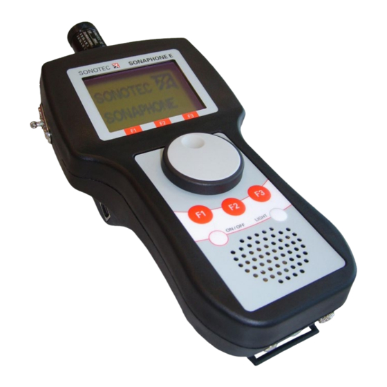
Page 18: Sonaphone E Connections, Control- And Display Elements
SONAPHONE ® SONAPHONE E connections, control- and display elements Ultrasonic-probe connector Surface temperature sensor Fastener for connector carrying shoulder strap Display Rotary knob with USB interface integrated push button Function buttons „F1-F3“ ON/OFF button LIGHT button Integrated speaker Headphone connector... -
Page 19: Operation
SONAPHONE ® 5 Operation Insert the batteries Death or serious injury possible. Incorrect operation, damage to the device as well as damage to accessories can impair the explosion protection. Never open the battery cover in a hazardous area. Never change the batteries in a hazardous area, with an active USB connection or when the power is on. - Page 20 SONAPHONE ® 3. Press down the battery compartment and pull it out of the unit. Operating Manual – Revision: 2.4 | 2020-11-17 Page 20 of 66...
- Page 21 SONAPHONE ® 4. Take the batteries out of the battery block. 5. Insert new batteries into the block. Observe correct arrangement of the polarity of the batteries on the upper side of the battery block. 6. Re-insert the battery compartment into the casing. 7.
-
Page 22: Starting Up The Unit
The following is shown on the display*: 16.02.2007 11:24:58 20°C log / 40kHz Son de: L60 Prüfer: SONOTEC Hold Menü 6 Currently available functions Battery or USB operation battery status indicator of keys “F1-F3”... -
Page 23: General Settings
To switch the unit on or off press the ON/OFF button. Depending on the intended use, connect the appropriate probe or the temperature sensor to the SONAPHONE E (see Section: Using the probes). A probe for structure-borne ultrasound is used for locating leaks. The ultrasonic value is besides the magnitude of the sound source also dependent on the probe’s direction and distance from the sound source. -
Page 24: Volume Adjustment
SONAPHONE ® Volume adjustment When the rotary knob is turned, a volume bar and an intensity value are displayed for about two seconds, as shown below: 16.02.2007 11:24:58 20°C Volume -24dB Turning the rotary knob clockwise increases the volume and turning it anti-clockwise decreases the volume. -
Page 25: Max" Function
SONAPHONE ® “Max” function The F1 key activates the “Max” function. In this state, the number displayed corresponds to the maximum ultrasonic value and the intensity bar to the current ultrasonic value. The activation of the “Max” function is signaled by highlighting the function key description: 16.02.2007 11:24:58 20°C... -
Page 26: Hold" Function
SONAPHONE ® “Hold” function Press the F2 function key to activate the “Hold” function. This serves to register ultrasonic values, for example, if the display is not visible at the moment of testing. Thereby, the ultrasonic values, which was recorded at the moment the F2 key was pressed, is stored in the display. -
Page 27: Main Menu
SONAPHONE ® Main menu Menu structure Data Logger Test Parameter Setup Single test Averaging time Date/Time Tester Auto-Power-Off Long-time test Mixer Frequency Auto-Light-Off Mode Contrast Temperature Language Operation There is a choice of three menu items in the main menu: the data logger for storing the test values, the test parameters for changing all parameters relevant to the test and the setup for changing the device’s parameters. -
Page 28: Data Logger
SONAPHONE ® Data logger General information Ultrasonic values and temperature test values can be stored in the data logger. The data record includes the date, the tester (maximum eight characters), the test site (maximum 16 characters), the type of probe used, the ultrasonic values and the temperature. -
Page 29: Long-Time Test
SONAPHONE ® Long-time test Records in different test modes are not comparable. For comparative tests, make absolutely sure that you have selected the same test mode (see chapter ‚Setting the test mode‘, page 40). Once the Long-time test has been selected, a summary of all Long-time tests created until then appears, showing the respective test site and the date of creation: Name... - Page 30 SONAPHONE ® Create new Long-time test To create a new Long-time test, press function key F2 to open a new screen: 00:00:30 17°C Parameter Start Setup Ultrasonic test value Scale for the ultrasonic test value Test duration Scale for the temperature test value Temperature Operating Manual –...
- Page 31 SONAPHONE ® To set the testing parameters, open the parameter menu using the function key “F1”. In order to make adjustments to the display of the Long- time test, or to end the Long-time test, the menu item “setup” has to be opened by pressing function key “F3”: 00:00:30 17°C Parameter...
- Page 32 When this menu is opened, the start of the Long-time test is set to “Auto”. The SONAPHONE E will thus start the Long-time test automatically at the time that has been set. If the time entered is earlier than the present time, the test is started immediately.
- Page 33 SONAPHONE ® Start the Long-time test The Long-time test can be manually started in the measuring screen by pressing function key F2: Remaining testing time Ultrasonic Temperatur test value test value 00:00:14 17°C Stop The ultrasonic test values are represented by a solid line, and the temperature values by a dotted line.
- Page 34 Now, you have the option of deleting the Long-time test or viewing the test values in form of a diagram. Long-time test Info Long-time test Info Motor 1 Test place Tester SONOTEC Date 05.03.07 Time 14:17:03 Duration 00:01:00 Back...
- Page 35 Press function key F2 in the detail screen to delete the current data record. As a safety measure, you are asked if this record should definitively be deleted: Long-time test Info Delete dataset Motor 1 Test place Tester SONOTEC Are these Data Date 05.03.07 to be deleted? Time 14:17:03 Duration...
-
Page 36: Single Test
SONAPHONE ® Start/overwrite Long-time test selected By pressing function key “F3” you have the option of starting a Long-time test that is already parameterized, or overwriting an existing Long-time test. Single test Once the individual test has been selected, a summary of all individual tests created previously, with their respective testing sites and corresponding status, appears. - Page 37 A Single test is edited or created in the following menu: Test place MOTOR Tester SONOTEC Save The character to be edited is selected by pressing the rotary knob and set by turning it. To edit the last character again press the Button “F1”. The character sets (ABC :;<) are switched over by...
-
Page 38: Test Parameters
Only the test parameters are reset to the initial settings. Setting the averaging time The SONAPHONE E provides the option of averaging the test values recorded over a variable period. The time is set between 0 and 10 seconds in half second increments in the Averaging time menu. By turning the rotary knob the settings can be changed and stored in the device. -
Page 39: Setting The Tester
SONAPHONE ® Setting the tester In this menu, you have the option of entering 8-character-long designations for the tester. To switch between character sets (ABC :;<), press function key “F2”. Tester SONOTE Save The character to be edited is selected by pressing the rotary knob and set by turning it. -
Page 40: Setting The Test Mode
SONAPHONE ® Setting the test mode The SONAPHONE E has three different display modes for the ultrasonic test value: Mode Scaling Linear 0 ... 240 Logarithmic (log) 0 ... 140 (= Default Value) dBµV -3.0 ... 63.5 (Display ≤ 3.0: --.--) (Microphone voltage 1 µV = 0 dBµV) -
Page 41: Settings (Device)
Auto Power Off The Auto–Power Off function allows the SONAPHONE E to be switched off automatically after a set length of time. Times between 1 and 25 minutes can be set in one minute increments by turning the rotary knob. -
Page 42: Auto Light Off
Language The menu prompts on the SONAPHONE E can be either in German or in English. This is set in the language menu by turning the rotary knob. Press function key F1 to return to the previous menu and F3 to return to the test mode. -
Page 43: Using The Probes
When using the ultrasonic probe L60 in Ex zone 0, it is imperative that it is connected via the probe extension cable and the housing is connected to the local potential equalization. Only the grounding kit supplied by SONOTEC should be used for this purpose. ®... - Page 44 SONAPHONE ® When placing the directional tube onto the air-borne probe L50 the tube could detach from the rubber grommet and damage the probe grid. Put the rubber grommet very carefully over the probe and never push with the tube. The precision of location is increased by mounting the directional tube.
-
Page 45: Structure-Borne Sound Probe L61 For Valve Inspection (Oil And Water Resistant)
When using the ultrasonic probe L61 in Ex zone 0, it must be connected via the probe extension cable and the housing must be connected to the local potential equalization. Solely the grounding set supplied by SONOTEC should be used for this purpose. ®... -
Page 46: Structure-Borne Sound Probe L62 For Long-Time Tests And Detection Of Bearing Wear, Steam Trap Testing
SONAPHONE ® Structure-borne sound probe L62 for long-time tests and detection of bearing wear, steam trap testing Death or serious injury possible. Incorrect operation, damage to the device as well as damage to accessories can impair the explosion protection. Prevent friction and impact sparks that could occur, for example, when the probe is dropped. - Page 47 SONAPHONE ® Note! For optimizing the test procedure the mixer frequency of the device can be changed (section 5.7 page 39) between 20 and 60 kHz in 2 kHz increments. Changing the mixer frequency affects the shown test values directly. In order to ensure reproducibility, values that have to be compared must be recorded with identical mixer frequencies.
-
Page 48: Flexible Air-Borne Sound Probe L63
SONAPHONE ® Flexible air-borne sound probe L63 Death or serious injury possible. Incorrect operation, damage to the device as well as damage to accessories can impair the explosion protection. When working with the L63 probe, never work in the vicinity of exposed live parts or without visual contact in areas unknown to you. -
Page 49: Using Accessories
SONAPHONE ® 7 Using accessories Telescoping rod Death or serious injury possible. Incorrect operation, damage to the device as well as damage to accessories can impair the explosion protection. When working with the telescopic rod, never work in the vicinity of exposed live parts or without visual contact in areas unknown to you. -
Page 50: Surface Temperature Sensor
SONAPHONE ® Surface temperature sensor In general, temperatures in the range of 0 °C ... 800 °C can be measured. In explosive atmospheres, maximum temperatures of up to 450 °C will occur. The surface temperature sensor can either be plugged into the SONAPHONE E directly or by using the extension cable. -
Page 51: Using The Grounding Kit
When using the ultrasonic probes L60 and L61 in Ex-zone 0, the casing of the probes must be connected to the local equipotential bonding conductor. Only the grounding set supplied by SONOTEC GmbH may be used for this purpose. Operating Manual – Revision: 2.4 | 2020-11-17... -
Page 52: Connecting 'Additional Sensors
® SONOTEC ® Allowed 'additional sensors' must be offered by SONOTEC ® accessories. If the additional sensor is connected, the complete device set may only be used in zones 1 and 2 (protection level drops to ib). -
Page 53: Pc Connection & Data Transfer
SONAPHONE ® 8 PC connection & data transfer Installation of ‘SONAPHONE Communicator’ under Windows ® The SONAPHONE E can be connected to a computer using a USB ® cable. ‘SONAPHONE Communicator’ software is needed for the device ® communication with the computer. This contains all necessary drivers to log the SONAPHONE E into the operating system and to ensure a power ®... - Page 54 Contains all necessary basic drivers for manual installation of SONAPHONE ® Operating_manual Operating Manual (DE | EN) Description firmware update (DE | EN) SONOTEC-Driver Driver Setup for automatic installation Setup.exe (Installation program) Start the <setup.exe> manually from installation CD. Operating Manual – Revision: 2.4 | 2020-11-17...
- Page 55 SONAPHONE ® After the start the following window appears: After clicking on <Next>, the setup automatically checks whether you have already installed the driver for the SONAPHONE E. If this has not ® yet been done, the following window appears: Click on <Yes>...
- Page 56 SONAPHONE ® If the device is already connected to the PC, please disconnect it, start the installation with <Next> and follow the instructions. Continue with the driver installation by clicking on <OK>: The Found New Hardware Wizard will start. By clicking on <Next> the driver installation will be executed.
- Page 57 SONAPHONE ® The following window appears: Click on <Next>. The following window informs about the further procedure: Continue the installation process by clicking on <OK>. Operating Manual – Revision: 2.4 | 2020-11-17 Page 57 of 66...
- Page 58 SONAPHONE ® Click on <Finish> in the following window to exit the setup wizard and complete the installation process. Note! If the above message box does not appear at startup of the "SONAPHONE Communicator", either no SONAPHONE E is ® ®...
-
Page 59: Power Supply Via Usb
SONAPHONE ® Power supply via USB Death or serious injury possible. Incorrect operation, damage to the device as well as damage to accessories can impair the explosion protection. Connect the SONAPHONE E to a computer only with the battery ® cover closed and outside the hazardous area. - Page 60 SONAPHONE ® If the USB symbol appears in the upper right corner after pressing the <ON/OFF> button, the switchover was successful. Otherwise, press the <ON/OFF> key again. If the unit is switched off by pressing the <ON/OFF> key, it is not possible to supply power via USB. Note! If the message window shown above does not appear when starting the "SONAPHONE...
-
Page 61: Cleaning
SONAPHONE ® 9 Cleaning Damage to SONAPHONE E possible. Aggressive cleaning agents ® may attack the plastic housing and impair the mechanical stability. The use of cleaning agents containing solvents is prohibited. Use damp cloths to clean the device and all accessories. Operating Manual –... -
Page 62: Troubleshooting And Self-Help In Case Of Errors
SONAPHONE ® 10 Troubleshooting and self-help in case of errors Not every malfunction must be an actual defect in the equipment. You save time and money if you can eliminate simple causes of faults yourself. The following information should help you: Fault Possible cause Remedy... -
Page 63: Technical Specifications
SONAPHONE ® 11 Technical specifications Operating frequency Ca. 40 kHz (20… 60 kHz in 2 kHz steps) Connections Ultrasonic sensor Temperature sensor Headphone USB interface (USB 2.0) Display Graphical display Background lighting Menu control Temperature 0 °C … 800 °C measurement range Dimensions 190 mm x 110 mm x 85 mm... -
Page 64: Warranty
SONAPHONE ® 12 Warranty SONOTEC GmbH provides a warranty of twelve months from the date of sale for the SONAPHONE E and their accessories. Within the warranty ® period, SONOTEC GmbH will correct all defects caused by faults in material or manufacturing without extra charge. SONOTEC GmbH will fulfil the warranty agreement by either repairing or replacing the defective device or component. - Page 65 SONAPHONE ® Operating Manual – Revision: 2.4 | 2020-11-17...
- Page 66 06112 Halle (Saale) Telephone: +49 (0)345 133 17-0 Fax: +49 (0)345 133 17-99 Email: mySONAPHONE@sonotec.de Internet: www.sonotec.de Americas SONOTEC US Inc. 190 Blydenburgh Rd Suite 8, 2nd floor Telephone: +1 631 / 415 4758 Email: sales@sonotecusa.com Internet: www.sonotecusa.com © SONOTEC GmbH All rights reserved.
Need help?
Do you have a question about the SONAPHONE E and is the answer not in the manual?
Questions and answers