Table of Contents
Advertisement
Quick Links
Advertisement
Table of Contents

Related Manuals for Sonotec SONAPHONE E


Summary of Contents for Sonotec SONAPHONE E
- Page 1 Ultrasonic Testing Device SONAPHONE E Operating Instructions...
- Page 2 © 2016 SONOTEC Ultraschallsensorik Halle GmbH All rights reserved The content of this operating manual is property of SONOTEC Ultraschallsensorik Halle GmbH and protected by copyright. No part of this manual may be translated, copied or reprinted without the explicit written consent of SONOTEC Ultraschallsensorik Halle GmbH.
-
Page 3: Table Of Contents
SONAPHONE E in hazardous areas ....... 5 Safety precautions for the SONAPHONE E in hazardous areas .............. 6 General safety precautions for the SONAPHONE E ..8 Scope of delivery ............ 9 Summary ................. 9 Arrangement of devices and accessories in the transport case ............... - Page 4 PC connection & data transfer ......40 Directory structure of the installation CD ....... 41 Installation for Windows XP / Windows Vista ....41 Installation for Windows 7 ..........43 Power supply via USB ........... 45 Trouble shooting ........... 46 Technical specifications ........
-
Page 5: Safety Precautions
(7) Only the ultrasonic probes L60 and L61 in connection with the probe extension cable are intended for the use in Ex-zone 0. The SONAPHONE E and the other accessories must not be taken into Ex- zone 0. (8) Only the equipment offered by SONOTEC as accessories may be used as extra sensors. -
Page 6: Safety Precautions For The Sonaphone E In Hazardous Areas
(2) The SONAPHONE E is intended for the use in areas in which there is a danger of explosion due to gases, vapours or mist accordance to the device marking. Do not use the device where there is a danger of dust explosions. - Page 7 SONAPHONE E’s plastic casing and affect its mechanical stability. (7) You are not allowed to open the SONAPHONE E or its accessories or to perform any unauthorised repairs. This could affect the explosion protection. Repairs may only be carried out by the manufacturer.
-
Page 8: General Safety Precautions For The Sonaphone E
0 and 40 °C. Store the unit at temperatures between -10 °C and +50 °C. (2) Make sure that you have a clear view of the SONAPHONE E and the probes at any time of operation. Never work with the probes or the telescoping rod in areas with live parts or areas you do not know exactly. -
Page 9: Scope Of Delivery
• SONAPHONE T ultrasonic transmitter • Spherical transmitter SONOSPHERE • Aluminum telescope bar • Transport case • PC software SONAPHONE E Communicator • USB cable • Operating instructions • Grounding set for probes L60 and L61 *) Please do notice, that the scope of delivery varies according to your order. -
Page 10: Arrangement Of Devices And Accessories In The Transport Case
Operating instructions Structure-borne sound probe SONAPHONE T Flexible air-borne sound probe Directional tube with tip Surface temperature sensor 10 Headphones Extension cable for the 11 SONAPHONE E temperature sensor Air-borne sound probe L60 with probe extension cable page 10 OM_SONAPHONE_E_en_Rev_2.3_2018-07-19... -
Page 11: Function Description
Ultrasound is generated due to friction caused by the flow of gases, liquids and solids in pipes and leakages. These ultrasonic signals are recorded by the SONAPHONE E, their intensity is shown on the display screen and made audible through speaker or headphones. As an option, surface temperatures can be measured with a temperature sensor. -
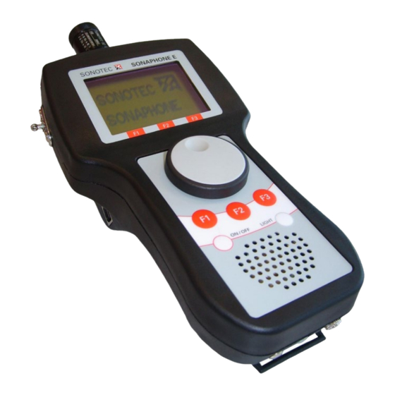
Page 12: Sonaphone E Connections, Control- And Display Elements
SONAPHONE E connections, control- and display elements Ultrasonic-probe connector Surface temperature sensor Fastener for carrying connector shoulder strap Graphical display Rotary knob with USB interface integrated push button Function buttons „F1-F3“ ON/OFF button LIGHT button Integrated speaker Headphone connector Screw for releasing the... -
Page 13: Operation
The battery block will move in the same direction as the locking screw. It is important to hold the battery block and the device firmly. Please contact SONOTEC in case the batteries are not available. page 13 OM_SONAPHONE_E_en_Rev_2.3_2018-07-19... - Page 14 3. Press down the battery compartment and pull it out of the unit. 4. Take the batteries out of the battery block. 5. Insert new batteries into the block, checking that the polarity is correct. An engraving on the top of the battery block illustrates the correct arrangement of the batteries.
- Page 15 6. Re-insert the battery compartment into the casing. 7. Tighten the locking screw of the battery compartment again. 8. Fasten the shoulder strap to the battery compartment lid. page 15 OM_SONAPHONE_E_en_Rev_2.3_2018-07-19...
-
Page 16: Starting Up The Unit
Starting up the unit The device is switched on by pressing the ON/OFF button. After displaying the splash screen, it switches automatically to the testing mode. The following is shown on the display: 16.02.2007 11:24:58 20°C log / 40k Hz Sensor: L60 Tester: SONOTE C Hold... -
Page 17: Check Mode
To switch the unit on or off press the ON/OFF button. Depending on the intended use, connect the appropriate probe or the temperature sensor to the SONAPHONE E (see Section: Using the probes). A probe for structure-borne ultrasound is used for locating leaks. The level of ultrasound is besides the magnitude of the sound source also dependent on the probe’s direction and distance from the sound source. - Page 18 Volume adjustment When the rotary knob is turned, a volume bar and an intensity value are displayed for about two seconds, as shown below: 16.02.2007 11:24:58 20°C Volume -24dB Turning the rotary knob clockwise increases the volume and turning it anti-clockwise decreases the volume.
- Page 19 “Max“ function The F1 key activates the “Max” function. In this state, the number displayed corresponds to the maximum ultrasound level and the intensity bar to the current ultrasound level. The activation of the “Max” function is signalled by highlighting the function key description: 16.02.2007 11:24:58 20°C...
-
Page 20: Main Menu
16.02.2007 11:24:58 20°C log / 40k Hz Sensor: L60 Tester: SONOTE C Hold Menu Press the rotary knob to store the currently displayed value, in other words the “Hold” value, in the individual test that is active. Press the F2 key again to deactivate the “Hold” function. Main menu Menu structure Data Logger... -
Page 21: Data Logger
The selected menu item is indicated by a dot in the selection circle: Menu Selection Data Logger Test Parameter Setup Data logger General information Ultrasound levels and temperature test values can be stored in the data logger. The data record includes the date, the tester (maximum eight characters), the test site (maximum 16 characters), the type of probe used, the ultrasound level and the temperature. - Page 22 Long-time test Once the Long-time test has been selected, a summary of all Long-time tests created until then appears, showing the respective test site and the date of creation: Name Halle 1 Halle 2 Pumpe Motor1 Back Selection In this menu, the user has a choice of four options: Pressing the rotary knob: Detailed information about the selected Long-time test...
- Page 23 Create new Long-time test To create a new Long-time test, press function key F2 to open a new screen: 00:00:30 17°C Parameter Start Setup Ultrasonic test value Scale for the ultrasonic test value Test duration Scale for the temperature test value Temperature To set the testing parameters, open the parameter menu using the...
- Page 24 00:00:30 17°C Parameter Start Setup Test Parameter Setup Test place / Tester 100°C max. Temperature Start max. Ultrasound Duration Close LTT! Interval Create Start Back See section Setting the tester for instructions on setting the test place and tester. In the start menu, the user can set the type and starting time of the Long-time test: Long-time test - Start 17.04.
- Page 25 When this menu is opened, the start of the Long-time test is set to “Auto”. The SONAPHONE E will thus start the Long-time test automatically at the time that has been set. If the time entered is earlier than the present time, the test is started immediately. Switching to “manual”...
- Page 26 Now, you have the option of deleting the Long-time test or viewing the test values in form of a diagram. Long-time test Info Long-time test Info Motor 1 Test place Tester SONOTEC Date 05.03.07 Time 14:17:03 Duration 00:01:00 Delete...
- Page 27 Long-time test Info Delete dataset Motor 1 Test place Tester SONOTEC Are these Data Date 05.03.07 to be deleted? Time 14:17:03 Duration 00:01:00 Back Delete Show To confirm, press function key F3, to cancel this action press F1. Start/overwrite Long-time test selected By pressing function key “F3”...
- Page 28 Test place MOTOR Tester SONOTEC Save The character to be edited is selected by pressing the rotary knob and set by turning it. To edit the last character again press the Button “F1”. Press “F3” to store both the tester’s name and the test site for the corresponding Single test.
-
Page 29: Test Parameters
Only the test parameters are reset to the initial settings! Setting the averaging time The SONAPHONE E provides the option of averaging the test values recorded over a variable period. The time is set between 0 and 10 seconds in half second increments in the Averaging time menu. - Page 30 Press “F3” to store the tester’s name in the device. Setting the mixer frequency In the SONAPHONE E, ultrasound is transformed into audible sound by a frequency conversion process. The unit provides the option of setting the working frequency via the mixer frequency.
-
Page 31: Settings
Setting the temperature display The SONAPHONE E provides the option of showing the temperature in °C or in °F. The switch over between the two types of display can be done in this menu. By turning the rotary knob the settings can be changed and stored in the device. - Page 32 Language The menu prompts on the SONAPHONE E can be either in German or in English. This is set in the language menu by turning the rotary knob. Press function key F1 to return to the previous menu and F3 to return to the test mode.
-
Page 33: Using The Probes
For precise fault location mount the tip onto the directional tube as well. Directional tip with o-ring Rubber grommet to attach on the probe L60 Directional tube If the leak cannot be located with the probe mounted directly on the SONAPHONE E, the probe extension cable can be used. page 33 OM_SONAPHONE_E_en_Rev_2.3_2018-07-19... -
Page 34: Structure-Borne Sound Probe L61 For Valve Inspection (Oil And Water Resistant)
The acoustic horn serves as attachment for airborne sound probe L60 to increase the range up to 5 … 6 meter. Structure-borne sound probe L61 for valve inspection (oil and water resistant) The L61 probe for structure-borne ultrasound is especially suitable for the determination of the ultrasound level at defective and damaged fittings (valves or gate valves). -
Page 35: Structure-Borne Sound Probe L62 For Long-Time Tests And Detection Of Bearing Wear
Structure-borne sound probe L62 for long-time tests and detection of bearing wear The probe L62 for structure-borne ultrasound is used to detect ultrasound in solid objects, e.g. for the poof of bearing wear. It has to be pressed gently by hand against the spot that has to be examined. -
Page 36: Flexible Air-Borne Sound Probe L63
Flexible air-borne sound probe L63 The flexible probe for air-borne ultrasound serves to detect ultrasound at areas that are particularly difficult to reach. CAUTION! When using the flexible air-borne sound probe L63, observe Item 2 of the general safety precautions. page 36 OM_SONAPHONE_E_en_Rev_2.3_2018-07-19... -
Page 37: Using Accessories
The telescoping rod is connected by cable to the SONAPHONE E. The length of the telescoping rod is continuously adjustable from about 1.70 metres to about 3 metres. To do this, loosen the black coupling ring between the inner and outer tubes of the telescoping rod. -
Page 38: Surface Temperature Sensor
For this purpose the temperature difference between the thermocouple junction (probe tip) and the reference junction is determined. The cold junction is the SONAPHONE E. page 38 OM_SONAPHONE_E_en_Rev_2.3_2018-07-19... -
Page 39: Using The Grounding Set
Only grounding supplied SONOTEC Ultraschallsensorik Halle GmbH may be used for this purpose. Before taking probes L60 or L61 into the Ex-zone 0, connect the grounding set in the following order! 1. Connect the probe L60 or L61 by means of the M4 screw. Screw the M4 screw into the side thread on the casing of the probe and tighten it with a suitable tool. -
Page 40: Pc Connection & Data Transfer
7 PC connection & data transfer CAUTION! The SONAPHONE E should only be connected to a PC if the battery compartment lid is closed! Opening the battery compartment lid while the unit is connected to the PC can result in damages to the unit! The SONAPHONE E can be connected to a computer using a USB cable. -
Page 41: Directory Structure Of The Installation Cd
Directory structure of the installation CD Installation for Windows XP / Windows Vista Installation of the driver unit When connecting the SONAPHONE E with the PC for the first time, a dialog for the installation of the driver unit opens: Step 1:... - Page 42 In case it will not work, press the key „Next >“. All drivers, which are needed for the operation of the SONAPHONE E, can be found in the index: „CD-drive:\Driver\“. In case there is no automatic identification as explained in step 2, you can choose menu item „Install from a list or specific location“, in order to choose the driver...
-
Page 43: Installation For Windows 7
By clicking on <Continue> the setup automatically checks if you already have installed a driver for the SONAPHONE E. If this has not happened already, the following window opens: By clicking on <Yes> the installation of the driver starts. In the next step you has to connect the SONAPHONE E with the Computer via USB cable. - Page 44 Click on <Install this driver software anyway> and in the following window on <Finish>. The driver installation is finished and the setup for the installation of the SONAPHONE E Communicator will be continued. Follow the instructions on the monitor. page 44...
-
Page 45: Power Supply Via Usb
USB. Notice: In case the window shown above does not appear after having started SONAPHONE Communicator, there either SONAPHONE E connected to the PC or the PC does not supply power for the SONAPHONE E. page 45 OM_SONAPHONE_E_en_Rev_2.3_2018-07-19... -
Page 46: Trouble Shooting
8 Trouble shooting Not every malfunction necessarily involves an actual defect of the equipment. Time and money can be saved if you are able to correct simple faults yourself. The following notes are intended to help do so: Fault Possible cause Remedy Device cannot be Batteries are empty... -
Page 47: Technical Specifications
9 Technical specifications Operating frequency Ca. 40 kHz (20-60 kHz width 2 kHz increments) Connections Ultrasonic sensor Temperature sensor Headphone USB interface (USB 2.0) Display Graphical display Background lighting Menu control Temperature 0 °C … 800 °C measurement range Dimensions 190 mm x 110 mm x 85 mm Weight Ca. -
Page 48: Warranty
10 Warranty SONOTEC Ultraschallsensorik Halle GmbH provides a warranty of twelve months from the date of sale for the SONAPHONE E and their accessories. Within the warranty period, SONOTEC Ultraschallsensorik Halle GmbH will correct all defects caused by faults in material or manufacturing without extra charge.
Need help?
Do you have a question about the SONAPHONE E and is the answer not in the manual?
Questions and answers