Table of Contents
Advertisement
Quick Links
s
Power Requirement
Power Output
Microwave Frequency
Magnetron
Timer
Outside Dimensions
Cavity Dimensions
Net Weight
Shipping weight
Speci cations subject to change without notice.
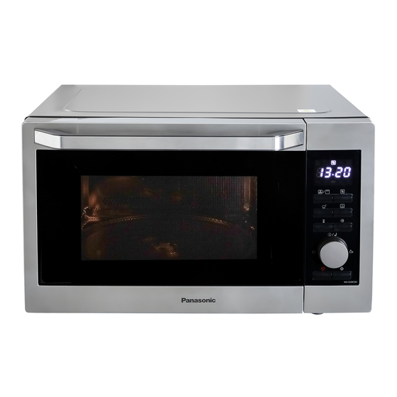
Model No.
30L
230 Volts AC 50 Hz
Microwave 1500W
2400W
Grill
Convection 2
400W
1000 Watts full microwave power
2,450 MHz
2M319J
0 ~ 9
0 min
520(D) mm
327
(
W) x
520
(H) x
(W) x
(H) x 351(D) mm
240.5
351
1
9.5 kg (approx.)
20.7 kg (approx.)
© Panasonic Corporation 201
copying and distribution is a violation of law
Order No. PMUK19100002C2
Microwave Oven
NN-C69KSMEPG
9 Unauthorized
Advertisement
Table of Contents

Subscribe to Our Youtube Channel
Related Manuals for Panasonic NN-C69KSMEPG


Summary of Contents for Panasonic NN-C69KSMEPG
- Page 1 Cavity Dimensions (W) x (H) x 351(D) mm 240.5 Net Weight 9.5 kg (approx.) Shipping weight 20.7 kg (approx.) Speci cations subject to change without notice. © Panasonic Corporation 201 9 Unauthorized copying and distribution is a violation of law...
-
Page 2: Safety Precautions
SAFETY PRECAUTIONS This device is to be serviced only by properly qualified service personnel. Consult the service manual for proper service procedures to assure continued safety operation and for precautions to be taken to avoid possible exposure to excessive microwave energy. PRECAUTIONS TO BE OBSERVED BEFORE AND DURING SERVICING TO AVOID POSSIBLE EXPOSURE TO EXCESSIVE MICROWAVE ENERGY... -
Page 3: Table Of Contents
CONTENTS (Page) SAFETY PRECAUTIONS - - - - - - - - - - - - - - - - - - - - - - - - - - - - - - - - - - - - - - - - - - - - - - - - - - - - - - - - - - - - - - - - - - - - - Inside front cover - - - - - - - - - - - - - - - - - - - - - - - - - - - - - - - - - - - - - - - - - - - - - - - - - - - - - - - - - - - - - - - - - -... -
Page 4: Power Level And Accessories
POWER LEVEL & ACCESSORIES ITEM DESCRIPTION Microwave Power for Variable Cooking Control Complement Power level 1000 Watts 750 Watts Medium 470 Watts 270 Watts Defrost 100 Watts Warm Combi Combi Rating Label Location Accessories Instruction manual Grill Tray Glass Tray Roller Ring Rack This microwave oven is designed for household use only. -
Page 5: Cautions
CAUTIONS Unlike other appliances, the microwave oven is MICROWAVE RADIATION high-voltage and high-current equipment. Personnel should not be exposed to the Though it is free from danger in ordinary use, microwave energy which may radiate from the extreme care should be taken during repair. magnetron or other microwave generating device if it is improperly used or connection. -
Page 6: Installations
INSTALLATIONS BEFORE YOU BEGIN, READ THE FOLLOWING INSTRUCTIONS COMPLETELY AND CAREFULLY. INSTALLING EARTHING INSTRUCTIONS IMPORTANT: THIS UNIT HAS TO BE Examine your microwave oven PROPERLY EARTHED FOR PERSONAL Unpack the oven, remove all packing material, SAFETY. and examine the oven for any damage such If your AC outlet is not grounded, it is the as dents, broken door latches or cracks in personal responsibility of the customer to have it... -
Page 7: Operating Instructions
OPERATING INSTRUCTIONS FEATURES 11 4 1. Door handle 2. Oven window 3. Air vents 4. Microwave feed guide (Do not remove.) 5. External air vents 6. Control panel 7. Power supply cord 8. Plug 9. Glass tray 10. Roller ring 11. -
Page 8: Operating Sequence
OPERATING SEQUENCE The following is a description of component functions during oven operation. 1. Microwave Cooking Speedy C o o k i n g Press "Micro/Grill/Conv./Combi" once, the screen In waiting state, press "START/+30SEC./CONFIRM" will display "P100". to cook with 100% power level for 30 seconds. Press "Micro/Grill/Conv./Combi"... - Page 9 OPERATING SEQUENCE The following is a description of component functions during oven operation. 1. Microwave Cooking Press Turn the dial to Press the dial Turn the dial to Press Start. Microwave. set the power to confirm the set the cooking level.
-
Page 10: Schematic Diagram
SCHEMATIC DIAGRAM... -
Page 11: Circuit Description
CIRCUIT DESCRIPTION power of microwave oven as POWER LEVEL. GENERAL DETAILS (refer to page 1-1) • The low voltage transformer supplies the necessary voltage to the micom controller when power cord is WHEN THE DOOR IS OPENED DURING plugged in. COOKING •... - Page 12 WHEN TOUCHING THE START KEY WITH THE COOKING CONVECTION SELECTED FUNCTION • The contacts of the primary switch and the secondary switch close the circuit. • A.C.voltage is applied to the grill heater and convection heater through each thermostat as shown by the solid line.
-
Page 13: Service Information
SERVICE INFORMATION TOOLS AND MEASURING INSTRUMENTS NECESSARY TOOLS NECESSARY MEASURING INSTRUMENTS Tools normally used for TV servicing are sufficient. • TESTER(VOLTS-DC, AC., Ohmmeter) Standard tools are listed below. • Microwave survey meter • Diagonal pliers - Holaday HI-1500 • Long nose pliers HI-1501 •... - Page 14 MEASUREMENT WITH OUTER CASE NOTES WHEN MEASURING REMOVED • Do not exceed meter full scale deflection. • The test probe must be removed no faster than • When you replace the magnetron, measure for 1 inch/sec (2.5 cm/sec) along the shaded area, microwave energy leakage before the outer case is otherwise a false reading may result.
-
Page 15: Measurement Of Microwave Power Output
MEASUREMENT OF MICROWAVE POWER OUTPUT • Microwave power output measurement is made with is measured while the microwave generator is the microwave oven supplied at its rated voltage and operating at full power. Magnetron filament heat-up operated at its maximum microwave power setting with time is not included. - Page 16 D. DOOR ASSEMBLY REMOVAL E. HIGH VOLTAGE TRANSFORMER REMOVAL 1) Open the door. 2) Remove two screws holding the Hinge 1) Discharge the high voltage capacitor. to the Cavity Ass'y. 2) Disconnect the leadwire from magnetron, high voltage CAUTION : Be careful not to damage Door C transformer, and capacitor.
- Page 17 H. AIR GUIDE ASSEMBLY REMOVAL J. REMOVING THE TURNTABLE MOTOR 1) Disconnect the leadwire from lamp, A.C Relay and 1) Remove the glass tray. monitor resistor and magnetron. 2) Remove the pulley shaft VERY CAREFULLY 3) Lay the unit down on its back. 2) Remove the screw to the cavity.
- Page 18 K. PCB ASSEMBLY REMOVAL L. INTERLOCK SYSTEM 1) Remove the control panel assembly from the 1) INTERLOCK MECHANISM cavity. The door lock mechanism is a device which has been specially designed to eliminate completely 2) Remove screws which hold the PCB to microwave activity when the door is opened during control panel.
-
Page 19: Interlock Continuity Test
INTERLOCK CONTINUITY TEST WARNING : FOR CONTINUED PROTECTION AGAINST EXCESSIVE RADIATION EMISSION, REPLACE ONLY WITH IDENTICAL REPLACEMENT PARTS. TYPE NO. KW3A FOR SWITCHS B. SECONDARY INTERLOCK SWITCH TEST A. PRIMARY INTERLOCK SWITCH TEST Disconnect the wire lead from the secondary When the door release button is depressed slowly switch. -
Page 20: Component Test Procedure
COMPONENT TEST PROCEDURE CAUTIONS 1. DISCONNECT THE POWER SUPPLY CORD FROM THE OUTLET WHENEVER REMOVING THE OUTER CASE FROM THE UNIT. PROCEED WITH THE TEST ONLY AFTER DISCHARGING THE HIGH VOLTAGE CAPACITOR AND REMOVING THE WIRE LEADS FROM THE PRIMARY WINDING OF THE HIGH VOLTAGE TRANSFORMER. - Page 21 COMPONENTS TEST PROCEDURE RESULTS Antenna Gasket Chassis Filament NOTE: When testing the magnetron, be sure to install the magnetron gasket in the correct position and be sure that the gasket is in good condition. HIGH VOLTAGE Measure the resistance. Normal: Momentarily indicates CAPACITOR (Ohm-meter scale: Rx1000) several ohms, and then...
- Page 22 COMPONENTS TEST PROCEDURE RESULTS FUSE Check for continuity of the fuse with an Normal Abnormal multi-meter. NOTE: If the fuse is blown, check the primary, the secondary, and the monitor switches, H.V.D. and H.V.C. before replacing the fuse. If the fuse is blown by improper switch operation replace the defective switch and the fuse at the same time.
- Page 23 COMPONENTS TEST PROCEDURE RESULTS Check for P.C.B. connector. L.V.Transformer of P.C.B Normal Abnormal Disconnect the 3 pin (Refer to schemetic diagram) connector from P.C.B. Cooking Start RELAY 2, RELAY 3 Relay 3 OF P.C.B. (Wire leads removed.) Relay 4 Note: Relay Relay 1: Lamp Turntable motor Relay 5...
-
Page 24: Trouble Shooting
TROUBLE SHOOTING WHEN YOU GET A COMPLAINT FROM YOUR CUSTOMER, EVALUATE THE COMPLAINT CAREFULLY. IF THE FOLLOWING SYMPTOMS APPLY, PLEASE INSTRUCT THE CUSTOMER IN THE PROPER USE OF THE MICROWAVE OVEN. THIS CAN ELIMINATE AN UNNECESSARY SERVICE CALL. CAUTIONS 1. Check grounding before checking for trouble. 2. - Page 25 (TROUBLE 1) The following visual conditions indicate a probable defective control circuit. 1. Incomplete segments. • Segment missing. • Partial segment missing. • Digit flickering (NOTE: Slight flickering is normal.) 2. Colon does not turn on or blink. 3. A distinct change in the brightness of one or more numbers in display. 4.
- Page 26 (TROUBLE 2) Oven does not operate at all ; Display window does not display any figures and no input is accepted. CONDITION CHECK RESULT CAUSE REMEDY Malfunction of the Replace primary Check continuity 1. Fuse blows. Continuity. monitor switch. and monitor of monitor switches.
- Page 27 (TROUBLE 3) Display shows all figures set, but oven does not start cooking while desired program times are set and START pad is touched. CONDITION CHECK RESULT CAUSE REMEDY Defective Replace Check continuity 1.Setting time does No continuity. secondary switch. secondary switch.
- Page 28 (TROUBLE 5) No microwave oscillation even though oven lamp and fan motor run (Display operates properly) CONDITION CHECK RESULT CAUSE REMEDY No microwave Disconnect the Defective P.C.B Replace P.C.B No continuity. assembly oscillation. wire leads from assembly relay 5 and check continuity Continuity.
- Page 29 (TROUBLE 6) Oven does not cook properly when programmed for the set power level (Operates properly on HIGH) CONDITION CHECK RESULT CAUSE REMEDY Defective P.C.B. Replace P.C.B. Output is full when Disconnect the Abnormal. assembly. assembly. you set lower wire leads from power level.
- Page 30 (TROUBLE 8) Convection REMEDY CONDITION CHECK RESULT CAUSE Convection Malfunction the Heater Heater. Abnormal. Replace. operating. heater. is not Normal. Thermostat and Malfunction the Abnormal. Replace. thermostat. relay3.(Convection) Normal. Replace or Wire connection. No continuity. Open or loosen. connect tightly. Lower tempera- Malfunction the Heater.
-
Page 31: Exploded View
EXPLODED VIEW INTRODUCTION OVEN CAVITY PARTS INTERIOR PARTS BASE PLATE PARTS DOOR PARTS LATCH BOARD PARTS CONTROL PANEL PARTS... - Page 32 DOOR PARTS...
- Page 33 CONTROL PANEL PARTS...
- Page 34 INTERIOR PARTS...
- Page 35 LATCH BOARD PARTS...
- Page 36 OVEN CAVITY PARTS R08A L05A...
- Page 37 BASE PLATE PARTS...
-
Page 38: Replacement Parts List
Do not use description of the part. 2. Important safety notice: Components identified by mark have special characteristics important for safety. When replacing any of these components, use only manufacture’s specified parts. NN-C69KSMEPG For Model: Safety Ref.No. Part Name&Description Pcs/Set Part No. - Page 39 REPLACEMENT PARTS LIST NN-C69KSMEPG For Model: 11002017000377 Brushless DC Motor 17470000009125 Thermostat 17470000001471 Thermostat 17470000001486 Thermostat 17470000001130 Quartz Heater 17470000008483 Quartz Heater 17470000001040 Heater 12270000006238 Heat Insulator G09A 12270000032279 Heat Insulator 12170000003416 Latch Board 12170000007332 Interlock Lever L02A 12170000007307 Interlock Lever...
-
Page 40: Schematic Diagram Of P.c.b
SCHEMATIC DIAGRAM OF P.C.B PC817 ZERO P54/EINT10 P52/EINT8 IC1_XIN P51/XIN IC1_XOUT P50/XOUT DSDA P00/DSDA DSCL P01/DSCL P02/AN0/EINT0 DC_FAN P31/COM6/SEG4 P03/SEG26/AN1/EINT1 P30/COM7/SEG5 KEY1 P27/SEG6 KEY2 P26/SEG7 KEY3 P25/SEG8 KEY4 P24/SEG9 KEY5 P23/SEG10 KEY6 P22/SEG11 DIAL_A P21/SEG12/AN15 S_CLK/TXD P20/SEG13/AN14/Txd1 S_DIN/RXD P10/SEG14/AN13/Rxd1...
Need help?
Do you have a question about the NN-C69KSMEPG and is the answer not in the manual?
Questions and answers