Twister T2 User Manual
Trim saver
Hide thumbs
Also See for T2:
- Owner's manual (72 pages) ,
- User manual (56 pages) ,
- User manual (60 pages)

Subscribe to Our Youtube Channel
Related Manuals for Twister T2


Summary of Contents for Twister T2
- Page 1 EUROPEAN MODEL T R I M S A V E R U S E R M A N U A L PN: 21-10090A_REV00 T W I S T E R T R I M M E R . C O M...
- Page 2 T W I S T E R T R I M M E R . C O M...
-
Page 3: Table Of Contents
T A B L E O F C O N T E N T S Important Safety Informa on Parts and Tools Assembled Trim Saver Assembly Controls Overview Opera on Inspec ons Cleaning Troubleshoo ng Warranty Informa on Specifi ca ons Spare Parts and Accessories Contact Us T W I S T E R T R I M M E R . -
Page 4: Important Safety Informa On
I M P O R T A N T S A F E T Y I N F O R M A T I O N This manual is for the Twister T2 Trim Saver vacuum– DANGER European model. In this manual, the Trim Saver vacuum will simply be referred to as the Trim Saver. - Page 5 Do not allow anyone to operate the Trim Saver unless it is fully assembled. • Do not switch on the Trim Saver unless it is connected to the T2 trimmer. • Do not operate the Trim Saver in an environment warmer than 30 C.
- Page 6 I M P O R T A N T S A F E T Y I N F O R M A T I O N • Clean the Trim Saver regularly. • Ensure the Trim Saver is powered off before conduc ng any maintenance. •...
-
Page 7: Parts And Tools
P A R T S A N D T O O L S Parts: Components Fig. 1 T W I S T E R T R I M M E R . C O M p g | 5... - Page 8 P A R T S A N D T O O L S Reference Descrip on Part Number Quan ty Caster 23-0146 Base Plate 23-0215 CS-18E Motor Support 11-10288A Lid Holder 23-0208 Saddle Support 23-0231 Hose Saddle 23-0198 3hp Euro Vacuum Fan and Motor Assembly 23-10168A Switch Mount 11-10287A...
- Page 9 P A R T S A N D T O O L S Parts: Fasteners The fasteners are placed in labelled bags that pertain to the diff erent stages of assembly. For easiest assembly, do not open these bags un l the instruc ons say to do so. Fig.
- Page 10 P A R T S A N D T O O L S Parts: Cable Supports Fig. 3 Reference Descrip on Part Number Quan ty Cable Tie Mount 15-10380 4” Cable Tie 15-0112 Tools Needed Fig. 4 Reference Descrip on Quan ty ⁄...
-
Page 11: Assembled Trim Saver
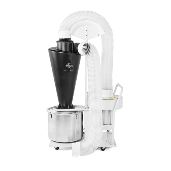
A S S E M B L E D T R I M S A V E R HOSE SADDLE CLEANING FLANGE CYCLONE ASSEMBLY HOSE CUFF LID HOLDER BIN LID START/STOP SWITCH MOTOR SUPPORT CASTER Fig. 5 6” HOSE HOSE CUFF SADDLE SUPPORT FILTER ADAPTER CART HANDLE... -
Page 12: Assembly
A S S E M B L Y Step 1: Attach the Casters to the Base Plate Open fastener bag A. Bag A contains: • Sixteen ⁄ –18 x ⁄ Hex Head ” ” Bolts • Sixteen ⁄ ” Star Lock Washers. Secure the casters to the base plate using all 16 bolts and star locks washers (see Fig. - Page 13 A S S E M B L Y Fig. 9 Fig. 10 Step 3: Attach the Motor Support to the Base Plate Open fastener bag C. Bag C contains: • Four ⁄ ”–18 x ⁄ ” Hex Head Bolts • Four ⁄...
- Page 14 A S S E M B L Y Fig. 12 Fig. 11 Align the base of the saddle support with the lid holder’s four center bolts holes. Ensure the pole-side of the base is facing the wide end of the lid holder (see Fig. 11). Secure the saddle support to the base plate using four ⁄...
- Page 15 A S S E M B L Y Fig. 14 Fig. 15 Step 6: Attach the Motor Assembly and Switch Mount to the Motor Support The vacuum motor is heavy and fragile. Use two people WARNING to complete this step. Open fastener bag E.
- Page 16 A S S E M B L Y Fig. 16 Fig. 17 Slide the switch mount in between the le side of the motor and washers (see Fig. 17). Reaching through the two large holes in the motor support, secure the star lock washers and nuts over the ends of the bolts (see Fig 18).
- Page 17 A S S E M B L Y Fig. 20 Fig. 19 Step 8: Attach the Start/Stop Switch to the Switch Mount Open fastener bag M. Bag M contains: • Four ⁄ ”–20 x ⁄ ” Hex Head Bolts • Four ⁄...
- Page 18 A S S E M B L Y Fig. 21 Fig. 22 Step 10: Secure the Cables Place the four cable e mounts in the bo om of the motor support, and push un l a click is felt (see Fig. 22). Thread cable es through all four cable e mounts.
- Page 19 A S S E M B L Y Fig. 25 Fig. 24 • Eight ⁄ ”–18 x ⁄ ” Hex Head Bolts • Eight ⁄ ” Star Lock Washers. Align the fi lter adapter with the adapter gasket and the vacuum assembly outlet (see Fig.
- Page 20 A S S E M B L Y Fig. 27 Fig. 26 Step 13: Attach the Cyclone and Bin Lid to the Lid Holder Open fastener bag H. Bag H contains: • Six ⁄ ”–20 x 1” Hex Head Bolts* •...
- Page 21 A S S E M B L Y Fig. 28 Fig. 29 Secure the silicone washers, then the fl at washers and nyloc nuts over the ends of the bolts (see Fig. 28). Step 14: Attach the Bin Place the lower lid gasket around the stainless steel bin lip.
- Page 22 A S S E M B L Y Fig. 31 Fig. 32 Place a hose cuff on each end of the hose (see Fig. 31) Slide a hose clamp over each hose cuff (see Fig. 31). Apply isoproyl alcohol or dish soap to the cyclone outlet. This will make sliding on the hose cuff...
- Page 23 Tighten the hose clamp. Step 18: Attach the Trim Saver to the T2 Trimmer Follow the Ini al Setup instruc ons in the T2 User Manual to a ach the Trim Saver to the T2 trimmer. T W I S T E R T R I M M E R . C O M...
-
Page 24: Controls Overview
C O N T R O L S O V E R V I E W MOTOR SPEED DIAL VFD SCREEN VACUUM DIRECTION DIAL VFD POWER AND TROUBLESHOOTING LOCKOUT SWITCH KEYPAD Fig. 34 Start/Stop Switch START BUTTON STOP BUTTON Fig. 35 p g | 2 2 T W I S T E R T R I M M E R . -
Page 25: Opera On
VFD without guidance from Keirton Technical Support. To operate the Trim Saver: Ensure the Trim Saver and T2 are fully assembled and safely connected by a hose. Ensure the motor speed dial on the VFD is at maximum speed (see Fig. 36). -
Page 26: Inspec Ons
To ensure op mal performance of the Trim Saver, the DANGER following inspec ons should be made on a weekly basis*. Ensure the Trim Saver and T2 are unplugged and all TURN OFF ALL MOTORS, THEN motors have come to a complete stop before conduc ng UNPLUG THE TRIM SAVER any inspec ons. -
Page 27: Cleaning
C L E A N I N G To ensure op mal performance, the Trim Saver should be DANGER cleaned regularly using the following steps: ENSURE THE TRIM SAVER IS Step 1: Disassemble the Trim Saver UNPLUGGED AND THE PLUG IS Ensure the Trim Saver and trimmer have COVERED BEFORE CLEANING TO been safely switched off... - Page 28 C L E A N I N G Fig. 38 Fig. 39 Pull the hose cuff s free from the inlets and outlets (see Fig. 38). Unscrew the hose cuff s from the hoses. Detach the Cyclone Outlet: Remove all six wing nuts from the cleaning fl ange (see Fig. 39). Remove the cyclone outlet and cleaning fl...
- Page 29 Remove the cyclone, bin lid, and gaskets. Step 2: Clean the Trim Saver The Trim Saver can be cleaned manually, or it can be le to clean in the Twister UltraClean ultrasonic cleaning system. Fig. 41 Manual Cleaning Clean the small, removable components: Soak the fi...
- Page 30 C L E A N I N G Do not rinse the motor assembly or electrical Rinse the hoses and cyclone. components with water. Spray the hoses and cyclone with isopropyl alcohol or another sani zer. Allow the sani zer to evaporate. UltraClean Cleaning Clean only the removed components in the UltraClean (see the UltraClean User Manual).
-
Page 31: Troubleshoo Ng
• The suc on is too high. Solution: Ensure the Trim Saver and T2 are unplugged and all motors have come to a complete stop. Increase the T2’s lt. If increasing the machine’s lt does not solve the problem, purchase a Vacuum Bypass to reduce suc on (see Bypass on page 34). - Page 32 T R O U B L E S H O O T I N G Solution: Ensure the Trim Saver and T2 are unplugged and all motors have come to a complete stop. If the fi lter adapter is too close to a wall, relocate the Trim Saver at least 4 from any wall.
-
Page 33: Warranty Informa On
W A R R A N T Y I N F O R M A T I O N Keirton will repair or replace any parts proven defec ve in material or workmanship without charge for a period of one year. The warranty period will begin on the date the machine is purchased by the ini al purchaser. - Page 34 W A R R A N T Y I N F O R M A T I O N • Improper electrical connec on • Neglect • Normal wear • Unapproved modifi ca ons including the use of unapproved replacement parts. Keirton assumes no risk and shall be subject to no liability for damages or loss resul ng from the specifi...
-
Page 35: Specifi Ca Ons
S P E C I F I C A T I O N S Product Number Product Number 23-10151A Opera ng Condi ons Airfl ow Capacity 1400CFM Opera ng Condi ons 950ACFM @ 5” w.g. Opera ng Temperature (ambient) 30 C (maximum) Sta c Pressure 12”... -
Page 36: Spare Parts And Accessories
Twister UltraClean - European Model 02-10031A Spare Parts Kits Item Product Number T2 Trim Saver Gasket Kit 27-10045A T2 Trim Saver Maintenance Kit* 27-10043A The maintenance kit includes hoses, hose cuff s, hose clamps, fi lter bags, and a vacuum bypass. -
Page 37: Contact Us
C O N T A C T U S Keirton Technical Support is available between 7 a.m. and 7 p.m. Pacifi c Standard Time seven days a week at: 1-888-254-3204 • support@keirton.com • T W I S T E R T R I M M E R . C O M p g | 3 5... - Page 38 T W I S T E R T R I M M E R . C O M...
- Page 39 T W I S T E R T R I M M E R . C O M...
- Page 40 T W I S T E R T R I M M E R . C O M...
Need help?
Do you have a question about the T2 and is the answer not in the manual?
Questions and answers