Table of Contents
Advertisement
Quick Links
Advertisement
Table of Contents

Related Manuals for CHART ULTRADOSER 2K


Summary of Contents for CHART ULTRADOSER 2K
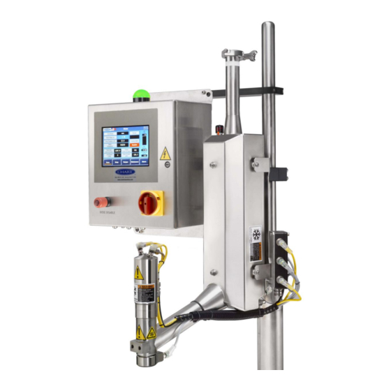
- Page 1 ULTRADOSER 2K USER MANUAL...
-
Page 2: Table Of Contents
Table of Contents Introduction ..............................4 Safety ................................6 Receiving Your UltraDoser 2K........................9 Overview and Utilities ..........................10 Product Specifications ........................10 Utility Requirements ......................... 10 UltraDoser Body Dimensions ........................11 UltraDoser 2K Components ......................... 13 Standard Components ........................13 Optional Components ........................ - Page 3 Appendix B – 2KA (Allen Bradley) Controller Wiring Diagram ............... 65 Appendix C – 2KS (Siemens) Controller Wiring Diagram ................. 66...
-
Page 4: Introduction
Chart’s service team at +1 408.371.4932. Service Chart’s UltraDoser 2K has been designed for years of safe and dependable operation. In the event service is required, please contact Chart at: Chart Inc. - Page 5 This manual is intended for use by Chart UltraDoser 2K operators. It is important to read and understand the information in this manual before installing or operating the system. This manual is provided by Chart to its customers as a courtesy and, except as expressly provided in this manual, CHART MAKES NO WARRANTIES, EXPRESS OR IMPLIED, REGARDING THE CONTENTS IN THIS MANUAL.
-
Page 6: Safety
Safety WARNING!: Your UltraDoser 2K may be fed by a vacuum insulated pipe system designed to contain pressurized, ultra-cold cryogenic liquids. These systems should only be worked on by trained personnel to avoid serious injuries such as freezing, oxygen deficient atmosphere and extremely high pressures. - Page 7 WARNING!: Accidental contact of liquid gases with skin or eyes may cause a freezing injury similar to a burn. Handle liquid so that it will not splash or spill. Protect your eyes and cover skin where the possibility of contact with liquid, cold pipes and equipment, or cold gas exists. Safety goggles or a face shield should be worn if liquid ejection or splashing may occur or cold gas may exit forcefully from equipment.
- Page 8 Nitrogen Nitrogen (an inert gas) is a simple asphyxiant. It will not support or sustain life and can produce immediate hazardous conditions through the displacement of oxygen. Under high pressure these gases may produce unconsciousness even though an adequate oxygen supply, sufficient for life, is detect. Nitrogen vapors in air dilute the concentration of oxygen necessary to support or sustain life.
-
Page 9: Receiving Your Ultradoser 2K
Upon arrival of the UltraDoser 2K, it is advised to immediately inspect for any signs of damage. If any damage occurred in shipping, claims must be filed with the shipping carrier immediately prior to unpacking the UltraDoser 2K. -
Page 10: Overview And Utilities
100-240 VAC 50-60Hz 110 W Portable Dura-Cyl dewar – 22 psi (1.5 bar) Liquid Nitrogen: Bulk Tank (House Fed) System (with Chart Phase Separator) - – 100 psi (6.9 bar) Maximum flow rate 15 gallons (56 liters) per hour 60 to 100 psi (4.1 to 6.9 bar) -
Page 11: Ultradoser Body Dimensions
UltraDoser Body Dimensions Shown with Standard Head... - Page 12 Shown with EP Head...
-
Page 13: Ultradoser 2K Components
Mounting Bracket Assembly The UltraDoser unit is supplied with a mounting bracket assembly. The assembly consists of the bracket attaching to the UltraDoser unit and two clamps. These clamps are designed to fit on Chart’s support stand or 1-1/2” stainless steel rod. -
Page 14: Optional Components
0.040”, 0.050”, and a 0.060” The size of the dosing nozzle directly affects the amount of LN nozzles ship loose with the UltraDoser 2K system. Custom sizes may be ordered from Chart. Drain Plug A drain plug is located on the back of the UltraDoser unit. When removed, this allows the LN to drain from the UltraDoser body. -
Page 15: Installation
Installation Application Evaluation The UltraDoser 2K can be used for both inerting and pressurization applications. The application must be evaluated to determine the ideal location of the dosing head on the filling line. Inerting – Inerting is the process of removing oxygen (O... -
Page 16: Mounting The Ultradoser Unit
Mounting the UltraDoser Unit Once the stand is installed, mount the UltraDoser unit on the stand using the supplied mounting bracket. -
Page 17: Connecting The Distribution Block
Connecting the Distribution Block The distribution block houses the electrical connectors and wiring interface between the operating parts of the UltraDoser unit and the 2K controller. There are five connections on the distribution block: Vent Heater (D-1) Provides +24VDC power to the vent heater. A green light on the cable connector indicates that power is being made available to the vent heater. -
Page 18: Installing The Nozzle
Installing the Nozzle Three nozzles are supplied with the UltraDoser 2K – 0.040”, 0.050”, and 0.060”. Custom sizes may be ordered from Chart. 1. Remove the dosing head heater. 2. Select a nozzle. 3. Insert the nozzle into the nozzle tool, threads out (Image 1). -
Page 19: Installing The Bottle Detect Sensor
See “Appendix A – Sensor Positioning” on page 63 for additional information. Installing the Timing Sensor The timing sensor is installed to detect filling line speed and must be installed for the UltraDoser 2K to operate properly. Chart provides a PNP 12mm inductive proximity sensor with the UltraDoser 2K system. -
Page 20: Installing The Encoder
Installing the Encoder The speed sensor is installed to detect filling line speed and must be installed for the UltraDoser 2K to operate properly. Chart provides a PNP 12mm inductive proximity sensor (Image 5) with the UltraDoser 2K system. Chart highly recommends a SICK encoder (Image 4) be installed in lieu of a PNP sensor to increase the resolution of the speed output for better performance of the UltraDoser 2K at higher line speeds. - Page 21 Follow the drawing below and mount with suitable hardware. Grounding is achieved by proper mounting of the encoder case. Ensure good electrical contact is made from the mounting flanges to an earthed bracket or other grounded mounting means. A mounting bracket (drawing below) is provided by Chart to assist in installation.
-
Page 22: Installing The 2K Controller
Installing the 2K Controller Locate the ideal location for the 2K controller. Brackets are supplied to mount the controller on the Chart prefabricated support stand or 1½”diameter rod or round bar . If Chart’s prefabricated brackets are not utilized, the controller’s mounting tabs can be utilized. - Page 23 The bottom of the 2K controller is the electrical “hub”. Input Power (J1) The 2K controller power cable (6ft) is connected to the 2K controller at port J1. Distribution Cable (J2) The 2K controller I/O (input/output) cable, a component of the distribution block, is connected to the 2K controller at port J2.
-
Page 24: 2K Controller Adjustments
Screen is a “read-only” screen; any changes need to be made on the respective screens. The only active buttons are located in the top left portion of the screen: the Chart logo and the country flag (see page 25 for additional information). From the “Home” Screen, the operator can navigate to other screens and functions using the navigation buttons on the bottom of the screen. -
Page 25: About
About On the [Home] screen, pressing the Chart logo will show the [About] screen. Chart’s contact information as well as the 2K controller’s PLC and HMI version and default IP address will be available on this screen. -
Page 26: Languages
Languages On the [Home] screen, pressing the flag will show the [Languages] sub-screen. Select the desired language setting from this screen. Flag Language English Mexico Spanish Brazil Portuguese English Spain Spanish Portugal Portuguese China Simplified Chinese Poland Polish Italy Italian IMPORTANT: Selecting a language automatically determines all settings including the date, pressure measurements, and distance measurements. -
Page 27: Setup
Setup Selecting the [Setup] navigation button will prompt two sub-navigation buttons: [System Settings] and [Calibration]. Access to these screens will require log in with user ID and password. See ‘Access and Passwords’ on page 27 for additional information. -
Page 28: Access And Passwords
Access and Passwords Changing any parameters on any screen requires a user ID and password. When accessing the changeable boxes a log-on dialog box will appear requesting a user ID and password. The 2K controller has been programmed to a default user and password as described below. User: A Password: A IMPORTANT: Once logged in, any and all user information is changeable. -
Page 29: System Settings
System Settings From [Setup], select [System Settings] to change system settings such as date/time, reset batch actuations, and hide/show the alarm banner. System Settings overview and meanings: Date/Time Set – The factory will program and set the current date and time. Any changes can be made at the ‘Set Date’... -
Page 30: Calibration
The distance delay and the dose duration will remain unchanged. IMPORTANT: Proper set up of the [Calibration] screen is essential to the successful operation of the UltraDoser 2K system. If after reading this section you are still unsure, please contact Chart’s service group at +1 408-371-9313. - Page 31 2. Enter the ‘Continuous Dosing Speed (CPM)’. This is the maximum speed at which the UltraDoser 2K will dose in discrete (pulse) mode. If the line speed exceeds this user entered value, the UltraDoser 2K will dose in continuous (stream) mode.
- Page 32 2. Enter the ‘Continuous Dosing Speed (CPM)’. This is the maximum speed at which the UltraDoser 2K will dose in discrete (pulse) mode. If the line speed exceeds this user entered value, the UltraDoser 2K will dose in continuous (stream) mode.
-
Page 33: Recipes
4. Enter the ‘Dose Duration’. This is the amount of time the system will dispense liquid from the dosing head (in milliseconds). Recipes Creating a Recipe 1. From the [Recipes] screen, press [Transfer] [Upload from PLC] to upload the dosing parameters from the [Calibration] screen. - Page 34 3. Name the recipes in the “Recipes Name” value. IMPORTANT: The “Recipes Name” value will be used to identify recipes on the [Home] screen. Enter Recipe Name Here 4. Press [Save]. This name will appear on the [Home] screen when the recipe is [Download(ed) to the PLC] (as opposed to the name under “Recipe”).
- Page 35 Activating a Recipe 1. Select and highlight the recipe you would like to use. 2. Press [Transfer] [Download to PLC] to activate the recipe. 3. Verify that the recipe has been activated. The “Recipes Name Value” should appear on the [Home] screen.
-
Page 36: Maintenance
Maintenance Selecting the [Maintenance] navigation button will prompt three sub-navigation buttons: [Maintenance Modes], [Graphs], and [Inputs/Outputs]. Access to these screens will require log in with user ID and password. See ‘Access and Passwords’ on page 27 for additional information. Maintenance Modes From [Maintenance], select [Maintenance Modes] to select and activate maintenance related features. - Page 37 Dosing Valve Disabled When the dosing valve is disabled, the maintenance modes become visible. Quick Service – the quick service button engages a solenoid which routes gaseous nitrogen (GN ) through the body to the dosing head. This is typically used to purging the system to ensure a clean pathway for liquid to flow.
-
Page 38: Graphs
Graphs From [Maintenance], select [Graphs] to view serves as the location for activation of the system once all the parameters have been set. Timing Analysis Graph – This circular graph is updated left to right every few seconds with current CPM data. - Page 39 Dose Delay Bar Graph – The graph starts at the left with the sensing of a container by the timing sensor and ends at the right with the sensing of the next timing sensor. This is the time between timing sensors and is the total time allocated for the Dosing Delay and the Dosing Duration.
-
Page 40: Inputs/Outputs
Inputs/Outputs Tower Light – troubleshoot the tower lights These are the three colored lights on top of the 2K controller. a) Green Light – press the ‘Force On’ toggle pushbutton to turn the green light on. Press the ‘Force Off’ toggle pushbutton to turn the green light off. The force action is enabled when the pushbutton is red. - Page 41 Liquid Level – calibrate and set alarm threshold for Liquid Level a) Raw Level – This is the raw reading from the PLC analog input. b) 0% Calibrate – Push this pushbutton when calibrating at the zero Liquid Level. c) Offset Level – After calibrating the liquid level at zero level by pushing the ‘0% Calibrate’ pushbutton the raw reading will become the Offset Level.
- Page 42 Inlet Pressure – calibrate and set alarm threshold for Inlet Pressure a) Raw Inlet Pressure – This is the raw reading from the PLC analog input. b) Offset Inlet Pressure – After calibrating the inlet pressure at zero level by pushing the ‘Offset’...
- Page 43 Bottle Sensor – set the functions of the bottle detect sensor The Bottle Sensor is used to detect bottles moving under the dosing head. a) Result – This is the current status of the Bottle Sensor. When illuminated green, bottles are being sensed, either from the sensor or the ‘Bypass Enabled/Disabled’...
- Page 44 Distribution Block – troubleshoot the distribution block sensors/connections These digital inputs and outputs replicate the lights on the Distribution Block. a) Speed Sensor (digital input) – Usually this is the status of the encoder pulses. b) Timing Sensor (digital input) – This is the status of the one per bottle sensor. c) Valve Confirm (digital input) –...
-
Page 45: Alarms
Alarms Two alarm screens are provided: Alarms and Alarm History. Alarms are displayed on the ‘Alarms’ screen when they are currently active and are retentively displayed on the ‘Alarm History’ screen. IMPORTANT: Alarm conditions do not stop liquid nitrogen dosing. IMPORTANT: Alarm conditions are shown on the [Alarms] screen. - Page 46 Warning Level Alarms – These warning alarms are provided to assist in troubleshooting any lack of functionality. These warning alarms trigger a solid yellow light. WARN #1 – Started Dosing with no shutdown faults. (green) – [gives a green starting reference on the alarm history screen.] WARN #2 - Dosing is Disabled.
-
Page 47: Alarm History
FAULT #33 - Internal PLC error. PWM Pulses not seen on input #6. – [Check the wiring to input #6 or 24VDC power.] FAULT #34 - Internal PLC error. PWM Pulses not seen on input #8. – [Check the wiring to input #8 or 24VDC power.] FAULT #35 - Internal PLC error. -
Page 48: Daily Operating Procedures
Daily Operating Procedures The UltraDoser 2K system can be fed by either a portable Dura-Cyl dewar or a bulk tank (house fed) liquid nitrogen system. Dura-Cyl Dewar Fed System IMPORTANT: LN is -320ºF (-196ºC). Any water and/or moisture can cause ice which will affect the performance of the UltraDoser 2K system. - Page 49 Purging with Gaseous Nitrogen The UltraDoser unit must only be purged with gaseous nitrogen. Chart recommends the UltraDoser unit be purged when not in use. However, this may not be practical for all operators. At a minimum, the UltraDoser unit should be purged to eliminate any water that may be inside the unit after installation and prior to startup,.
- Page 50 3. Connect the C-Flex hose to the liquid outlet on the full Dura-Cyl dewar using a 7/8” open end wrench or adjustable crescent wrench. IMPORTANT: The UltraDoser 2K will continue to dose properly until the liquid level inside the UltraDoser unit runs low. This feature gives the operator a reasonable window in which to change out the...
-
Page 51: Bulk Tank (House Fed) System
UltraDoser Controller IMPORTANT: LN is -320ºF (-196ºC). Any water and/or moisture can cause ice which will affect the performance of the UltraDoser 2K system. Providing a positive pressure of GN (also known as purging) to the UltraDoser unit before introducing LN into the body will eliminate many performance interruptions. - Page 52 The UltraDoser reservoir must also be purged when the nozzle becomes frozen shut. This section assumes a Y-Pattern valve and Purge Kit are installed upstream of the UltraDoser unit. Chart highly recommends each UltraDoser 2K be installed with a Y-Pattern valve and Purge Kit to isolate the UltraDoser unit from the LN source and to purge the UltraDoser unit to eliminate performance interruptions.
- Page 53 System Start Up This section assumes the Chart Phase Separator is full of liquid nitrogen. If this is not the case, ample time is needed to fill the Chart Phase Separator with liquid nitrogen before the UltraDoser 2K can start- 1.
-
Page 54: Service And Maintenance
Service and Maintenance Nozzle Change Out 1. Remove the dosing head heater. 2. Insert the nozzle tool into the nozzle area until the tool connects with the nozzle (Image 7). 3. Remove the nozzle with the driver in a counter-clockwise direction. Remove. 4. -
Page 55: Purging With Gaseous Nitrogen
Purging with Gaseous Nitrogen The UltraDoser unit must only be purged with gaseous nitrogen. Chart recommends the UltraDoser unit be purged when not in use. However, this may not be practical for all operators. At a minimum, the UltraDoser unit should be purged to eliminate any water that may be inside the unit after installation and prior to startup. -
Page 56: Common Replacement Parts
Common Replacement Parts Item No. Part Description Part No. ULTRADOSER PARTS UltraDoser Body 15170 Head Assembly EP Head Assembly (Optional) 1005 2.1.1 Dosing Stem (Valve) Assembly 670.38 2.1.2 Solenoid Valve Spare Assembly 2450.16 Head Assembly (Standard) 2.2.1 Dosing Stem (Valve) Assembly 2.2.2 Solenoid Valve Spare Assembly Dosing Head Heater (no cable included) -
Page 61: General Trouble Shooting
General Trouble Shooting Below are a few general trouble shooting guidelines. If after reading this section, the condition does not change or the condition is not covered in this section, please contact Chart’s service team at +1 408.371.4932. Condition: The safety relief valve is venting. - Page 62 Condition: No liquid from the dosing head. Possible Causes Actions There is insufficient liquid inside the UltraDoser Check the level of LN . If the level is empty or low, unit. open the supply valve. The unit is disabled. ...
-
Page 63: Warranty
MERCHANTABILITY OR FITNESS FOR A PARTICULAR PURPOSE OR USE, OTHER THAN OR WHICH EXTEND THOSE WARRANTIES EXPRESSED HEREIN. The original purchaser shall indemnify, defend and hold Chart harmless from any third party claims as a result of the use, sale, or lease of the LN... -
Page 64: Appendix A - Sensor Positioning
Appendix A – Sensor Positioning... - Page 65 Appendix B – 2KA (Allen Bradley) Controller Wiring Diagram...
- Page 66 Appendix C – 2KS (Siemens) Controller Wiring Diagram...
Need help?
Do you have a question about the ULTRADOSER 2K and is the answer not in the manual?
Questions and answers