Table of Contents
Advertisement
Quick Links
Advertisement
Table of Contents

Related Manuals for Stockmaster Navigator


Summary of Contents for Stockmaster Navigator
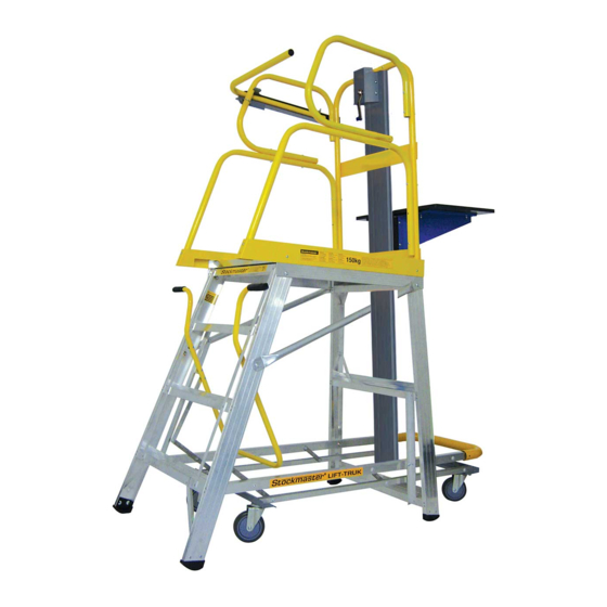
- Page 1 CL/INST01a Assembly Instructions * Pro Version shown...
- Page 2 Platform - Safety Rail Assembly IMPORTANT To avoid assembly problems follow these instructions exactly. Note : If assembling the platform with Folding Safety Rails first read the seperate instructions included with the Folding Safety Rail Bracket Kit. Step 1 Fix the Rear Safety Rail to the rear of the Platform Kickrail. Use the M6 x 45mm Patchlok bolts (blue coated) and screw in with the hexagon key leaving the bolt slightly loose (See illustration No.
- Page 3 Platform - Safety Rail Assembly M6 x 45 Patch-Lok M6 x 40 Illustration 1 Illustration 2 M6 x 65 M6 x 65 Illustration 3 Illustration 4 www.stockmastereurope.nl...
- Page 4 Platform - Safety Rail Assembly M6 x 65 Illustration 5 Illustration 6 NEXT: For PRO Models - Proceed to Rota-Gate Assembly NEXT: For Standard Models - Proceed to Ladder Frame Assembly www.stockmastereurope.nl...
- Page 5 Rota-Gate Assembly IMPORTANT To avoid assembly problems follow these instructions exactly. Step 1 Fasten the Angle Rotating Bracket to the Lower Side Safety Rail at A and B using two M6 x 40mm Bolts and Finger tight only Nyloc Nuts - .
- Page 6 Rota-Gate Assembly M6 x 40 M6 x 40 M6 x 40 Illustration 1 Illustration 2 Illustration 3 Illustration 4 www.stockmastereurope.nl...
- Page 7 Auto-Safe Gate Assembly IMPORTANT To avoid assembly problems follow these instructions exactly. Step 1 Remove the M6 x 65mm screw and nyloc nut at A from the LHS Upper Side Safety Rail as viewed from the entry point of the platform and discard. (See illustration No. 1) Step 2 Align the Rear Tab of the Auto-Safe Gate Housing with hole position A in the LH Side Upper Safety Railing.
- Page 8 Auto-Safe Gate Assembly M6 x 70 Illustration 1 Illustration 2 M6 x “U” Bolt M6 x “U” Bolt Illustration 3 Illustration 4 www.stockmastereurope.nl...
- Page 9 Ladder Frame Assembly IMPORTANT To avoid assembly problems follow these instructions exactly. Work Safely - Do not stand the frames upright when assembling. Place the frames in the positions as shown in the illustrations. Step 1 Lay the Rear Frame (without steps) on the floor. Check that the Flat Brace is at the floor level. If not, turn the frame over.
-
Page 10: Flat Brace
Ladder Frame Assembly Flat Brace Illustration 1 Illustration 2 M10 x 20 Illustration 3 Illustration 4 www.stockmastereurope.nl... - Page 11 Ladder Frame Assembly M10 x 20 M10 x 20 Illustration 5 Illustration 6 www.stockmastereurope.nl...
- Page 12 Tube Brace Assembly IMPORTANT To avoid assembly problems follow these instructions exactly. Work Safely - Do not stand the frames upright when assembling. Place the frames in the positions as shown in the llustrations. Instructions for sizes with 4 to 7 steps including the platform Proceed to Control Handle Assembly There are no additional Tube Braces to be fitted to these sizes.
- Page 13 Tube Brace Assembly Nylon Spacer Nylon Spacer M10 x 20 M10 x 20 Illustration 1 Illustration 2 M10 x 45 M10 x 45 Illustration 3 www.stockmastereurope.nl...
-
Page 14: Control Handle Assembly
IMPORTANT To avoid assembly problems follow these instructions exactly. Work Safely - This assembly is done with the Stockmaster standing upright. Step 1 Stand the Ladder upright. Position the Control Handle in the Step Frame between the 2nd and 3rd steps. - Page 15 Control Handle Assembly M6 x 16 Illustration 3 Illustration 4 NEXT: For sizes with 4 to 5 steps incl. platform: Proceed to Mobilisation Assembly Instructions NEXT: For sizes with 6 to 14 steps incl platform: Proceed to Handrail Assembly Instructions www.stockmastereurope.nl...
-
Page 16: Handrail Assembly
To avoid assembly problems follow these instructions exactly. Work Safely - This assembly is done with the Stockmaster standing upright. Step 1 Fix the Handrail to the Platform Kickrail. Slide the Handrail into the Kickrail and rotate the handrail so that the lower end is over the Step. - Page 17 Handrail Assembly Illustration 3 www.stockmastereurope.nl...
- Page 18 To avoid assembly problems follow these instructions exactly. Work Safely - This assembly is done with the Stockmaster standing upright. Step 1 Fix the Mobilisation Rails (Rectangular Hollow Section - RHS) to the Frames at A & B (See illustration No. 1) Step 2 Using the M8 x 40 bolts, nuts and sleeves.
- Page 19 Mobilisation Assembly M8 x 40 IIllustration 1 Illustration 2 M8 x 40 Illustration 3 Illustration 4 www.stockmastereurope.nl...
- Page 20 M12 x 40 Illustration 5 Illustration 6 NEXT: Australian Standard AS 1892.1 Product Assembly is complete and your Navigator Ladder qualifies under Australian Standards AS 1892.1. You can proceed to User Instruction and Warranty Links. NEXT: User Instructions and Warranty links.
-
Page 21: Ballast Assembly
Ballast Assembly EN 131.7 !!! A IMPORTANT IMPORTANT !!! AVOID DAMAGE TO BALLAST TUBE !!! VOID DAMAGE TO BALLAST TUBE DO NOT DROP DO NOT OVERTIGHTEN ‘U’ BOLTS DO NOT DROP DO NOT OVERTIGHTEN ‘U’ BOLTS Instructions for sizes with 4 to 5 steps including the platform Product Assembly is Complete. - Page 22 Ballast Assembly EN 131.7 Inner Holes Outer Holes-B IIllustration 1 Illustration 2 Illustration 3 Illustration 4 www.stockmastereurope.nl...
-
Page 23: Warranty
Before use see the User Instruction Manual at www.stockmastereurope.nl Use this manual to form part of your Risk Assesment WARRANTY Thank you for choosing Stockmaster. Your safety is in good hands Register your 2 year warranty online at www.stockmastereurope.nl www.stockmastereurope.nl...
Need help?
Do you have a question about the Navigator and is the answer not in the manual?
Questions and answers