
Related Manuals for Hitachi RPIL-3.0UFE1NH


Summary of Contents for Hitachi RPIL-3.0UFE1NH
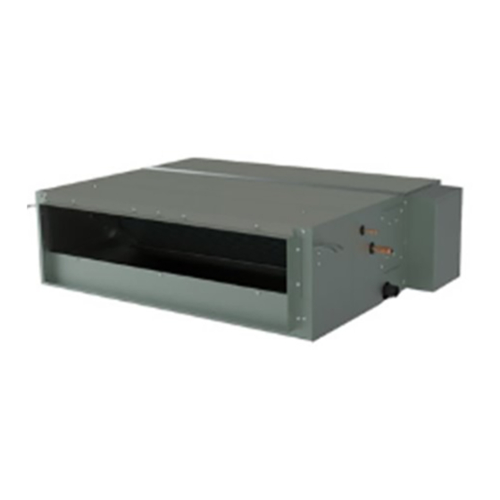
- Page 1 MONO SPLIT DC-INVERTER SERIES INDOOR UNITS DUCTED UNIT RPIL-3.0UFE1NH RPIH-3.5UFE1NH RPIH-4.0UFE1NH RPIH-5.0UFE1NH RPIH-6.0UFE1NH RPIH-6.5UFE1NH HO2019290HA...
-
Page 3: Table Of Contents
Contents Safety Precautions ............................. 1 Composition of the Air conditioner ......................6 Operation Manual ............................8 Special Remarks ............................8 Troubleshooting ............................8 Filter Cleaning .............................. 9 Installation and Maintenance ........................10 1 Safety Notice ............................10 2 Tools and Instruments for Installation ..................... 11 3 Installation of the Indoor Unit ........................ - Page 4 Caution Statements Alert Symbols The symbol refers to a hazard which can result in severe personal injury or DANGER death. The symbol refers to a hazard or an unsafe practice which may result in severe per- WARNING sonal injury or death. The symbol refers to a hazard or an unsafe practice which may result in minor per- CAUTION sonal injury, product or property damage.
- Page 5 Humidity 30%~80% • The numbers in the model represent the cooling capacity (HP). • For example, 3.0HP represents RPIL-3.0UFE1NH. • Heating and electric heating functions are not available for cooling only models. • This manual should be considered as a permanent part of the air conditioner and should remain with it.
-
Page 7: Safety Precautions
SAFETY PRECAUTIONS Safety Precautions Precautions for using R32 refrigerant The basic installation work procedures are the same as the conventional refrigerant (R22 or R410A). However, pay attention to the following points: WARNING 1 Transportation of equipment containing flammable refrigerants Pay attention to the fact that additional transportation regulations may exist with respect to equipment containing flammable gas. The maximum number of pieces of equipment or the configuration of the equipment permitted to be transported together will be determined by the applicable transport regulations. - Page 8 SAFETY PRECAUTIONS 6.6. No ignition sources • No person carrying out work in relation to a refrigeration system which involves exposing any pipe work that contains or has contained flammable refrigerant shall use any sources of ignition in such a manner that it may lead to the risk of fire or explosion.
- Page 9 SAFETY PRECAUTIONS The use of silicone sealants may inhibit the effectiveness of some types of leak detection equipment. Intrinsically NOTE: safe components do not have to be isolated prior to working on them. 8 Repairing intrinsically safe components • Do not apply any permanent inductive or capacitance loads to the circuit without ensuring that this will not exceed the permissible voltage and current for the equipment in use.
- Page 10 SAFETY PRECAUTIONS 13 Charging procedures • In addition to conventional charging procedures, the following requirements shall be followed: Ensure that contamination of different refrigerants does not occur when using charging equipment. Hoses or lines shall be as short as possible to minimise the amount of refrigerant contained in them. Cylinders shall be kept upright.
- Page 11 SAFETY PRECAUTIONS • Hoses shall be complete with leak-free disconnect couplings and in good condition. • Before using the recovery machine, check that it is in satisfactory working order, has been properly maintained and that any associated electrical components are sealed to prevent ignition in the event of a refrigerant release. •...
-
Page 12: Composition Of The Air Conditioner
COMPOSITION OF THE AIR CONDITIONER Explanation of symbols displayed on the indoor unit or outdoor unit This symbol shows that this appliance uses a flammable refrigerant. WA R N I N G If the refrigerant is leaked and exposed to an external ignition source, there is a risk of fire. - Page 13 COMPOSITION OF THE AIR CONDITIONER Remote Controller (Optional) You can control the air conditioner with the wired controller or remote controller. It is used for power ON/OFF, setting the operation mode, temperature, fan speed, etc. There are different types of remote controllers that can be used. Operation instruction will be further specified in remote controller’s manual.
-
Page 14: Operation Manual
OPERATION MANUAL Operation Manual Special Remarks • 3-minute protection after compressor stop To protect compressor, it will be off for at least 3 minutes once it is stopped. • 5-minute protection Compressor must run for at least 5 minutes once it is operated. During the 5 minutes, compressor will not stop even if the room temperature reaches the set temperature unless you use remote controller to turn off the unit (all indoor units can be turned off by user). -
Page 15: Filter Cleaning
OPERATION MANUAL 4 This is Not Abnormal • Odour from Indoor Unit Unpleasant odour diffuses from indoor unit after a long period of shutdown. Clean the air filter and panels or allow a good ventilation. • Sound from Deforming Parts When start or stop the system, a sound might be heard. -
Page 16: Installation And Maintenance
INSTALLATION AND MAINTENANCE Installation and Maintenance 1 Safety Notice WARNING • Installation should be performed by qualified personnel. (Improper installation may cause water leakage, electrical shock or fire.) • Install the unit according to the instructions given in this manual. (Incomplete installation may cause water leakage, electrical shock or fire.) •... -
Page 17: Tools And Instruments For Installation
INSTALLATION AND MAINTENANCE 2 Tools and Instruments for Installation Number Tool Number Tool Standard screwdriver Knife or wire stripper Vacuum pump Leveler Charge hose Hammer Pipe bender Churn drill Adjustable wrench Pipe expander Pipe cutter Inner hexagon spanner Cross head screwdriver Measuring tape 3 Installation of the Indoor Unit CAUTION... -
Page 18: Installation
INSTALLATION AND MAINTENANCE 3.2 Installation • Optimum air distribution must be ensured. • The air path must not be blocked. 3.2.1 Suspension bolts • Condensation has to drain properly. 1 Consider the pipe direction, wiring and maintenance • The ceiling must be strong enough to bear the weight of the carefully, and choose the proper direction and location for indoor unit. - Page 19 INSTALLATION AND MAINTENANCE 3.2.3 Installation of the indoor unit 3 After the adjustment, tighten the nuts and smear the thread locker on the suspension to prevent the nuts from loosening. The installation of the indoor unit is shown in Fig. 3.4. CAUTION Suspension bolts (4-M10 or W3/8) ( Field supplied )
-
Page 20: Refrigerant Pipe
INSTALLATION AND MAINTENANCE 4 Refrigerant Pipe DANGER Model Gas Pipe (mm) Liquid Pipe (mm) 3.0/3.5HP ∅15.88 ∅9.52 Use the refrigerant according to outdoor nameplate. When carrying 4.0/5.0/6.0/6.5HP ∅19.05 ∅9.52 out the leakage check and test, do not mix in the oxygen, the acetylene and the flammable and the reactive gas, because these Fig. -
Page 21: Drain Piping
INSTALLATION AND MAINTENANCE 5 Drain Piping • Install the drain piping. CAUTION • Make sure that the drain works properly. Drain piping connections: • Prepare polyvinyl chloride pipe with a 32mm outer diameter. • Do not connect the drain pipes directly to sewage pipes to avoid •... -
Page 22: Electrical Wiring
INSTALLATION AND MAINTENANCE 6 Electrical Wiring 6.1 General Check CAUTION • When clamping the wiring, use the included clamping material as shown in the Fig. 6.1 to prevent external pressure on the wiring connections, and then clamp firmly. • While performing wiring work, make sure that the wiring is proper and cannot cause the control box lid to stick up, then close the cover firmly. When attaching the control lid, make sure that you do not pinch any wires. -
Page 23: Changing Static Pressure
INSTALLATION AND MAINTENANCE 6.2 Changing Static Pressure The static pressure can be freely adjusted by using specific wired remote controller. Range of Static Model Function Code Set Pressure Function code 0-40, function code value equals static pressure value, 3.0HP 0-40Pa more than 40 is 40 Pa, Parameter code [default: 0 (25Pa)]... -
Page 24: Test Run
INSTALLATION AND MAINTENANCE NOTES: 1 Follow local codes and regulations when selecting field wires, and all above are the minimum size. 2 The wire sizes marked in the table are selected at the maximum current of the unit according to the European Standard, EN60335-1. - Page 26 They can take this product for environmental safe recycling. Specifications in this document are subject to change without notice, in order that Hitachi-Johnson Controls Air Conditioning, Inc. may bring the latest innovations to their customers.
Need help?
Do you have a question about the RPIL-3.0UFE1NH and is the answer not in the manual?
Questions and answers