Advertisement
RPIH-3.0HNAUNQ
RPIH-3.3HNAUNQ
RPIH-4.0HNAUNQ
RPIH-5.0HNAUNQ
RPIH-6.0HNAUNQ
RPIM-0.8HNAUNQ
In-the-
RPIM-1.0HNAUNQ
Ceiling Type
RPIM-1.3HNAUNQ
RPIM-1.5HNAUNQ
RPIM-1.8HNAUNQ
RPIM-2.0HNAUNQ
RPIM-2.3HNAUNQ
RPIM-2.5HNAUNQ
RPIL-0.8HNAUNQ
This manual is exclusively prepared for
R410A indoor unit. Please read this manual
in conjunction with corresponding manual for
outdoor unit.
RPIL-1.0HNAUNQ
RPIL-1.3HNAUNQ
RPIL-1.5HNAUNQ
RPIL-1.8HNAUNQ
RPIL-2.0HNAUNQ
RPIL-2.3HNAUNQ
RPIL-2.5HNAUNQ
RPIL-3.0HNAUNQ
RPIL-3.3HNAUNQ
RPIL-4.0HNAUNQ
RPIL-5.0HNAUNQ
RPIL-6.0HNAUNQ
P01590Q
ORIGINAL INSTRUCTIONS
Advertisement
Table of Contents

Related Manuals for Hitachi RPIH-3.0HNAUNQ


Summary of Contents for Hitachi RPIH-3.0HNAUNQ
- Page 1 RPIH-3.0HNAUNQ RPIL-1.0HNAUNQ RPIH-3.3HNAUNQ RPIL-1.3HNAUNQ RPIH-4.0HNAUNQ RPIL-1.5HNAUNQ RPIH-5.0HNAUNQ RPIL-1.8HNAUNQ RPIH-6.0HNAUNQ RPIL-2.0HNAUNQ RPIM-0.8HNAUNQ RPIL-2.3HNAUNQ In-the- RPIM-1.0HNAUNQ RPIL-2.5HNAUNQ Ceiling Type RPIM-1.3HNAUNQ RPIL-3.0HNAUNQ RPIM-1.5HNAUNQ RPIL-3.3HNAUNQ RPIM-1.8HNAUNQ RPIL-4.0HNAUNQ RPIM-2.0HNAUNQ RPIL-5.0HNAUNQ RPIM-2.3HNAUNQ RPIL-6.0HNAUNQ RPIM-2.5HNAUNQ RPIL-0.8HNAUNQ This manual is exclusively prepared for R410A indoor unit. Please read this manual in conjunction with corresponding manual for outdoor unit.
- Page 3 Declaration of Conformity (Manufacturer’s Declaration) Qingdao Hisense Hitachi Air-conditioning Systems Co., Ltd. Add: 218, Qianwangang Road, Economic & Technical Development Zone, Qingdao, P.R. China declares under its sole responsibility that the air conditioning models to which this declaration relates: RPIH-3.0~6.0HNAUNQ, RPIM-0.8~2.5HNAUNQ, RPIL-0.8~6.0HNAUNQ...
-
Page 4: Important Notice
This manual should be considered as a permanent part of the air conditioning equipment. Please keep it properly. ● Hitachi pursues a policy of continuous improvement in design and performance of products. The right is therefore reserved ● to change specifications without notice. -
Page 5: Checking Product Received
The standard operation method for the machine is described in the present manual. Please contact local dealer when problem arises. Hisense Hitachi shall not be held responsible for any consequence of the modification to machine performed without its written consent. - Page 6 Unit Description Part Name 3.1 Indoor Unit 3.2 Remote Control Before Operation Operation Mode Auto Control Cleaning of Filter Screen 7.1 Removing Filter Screen 7.2 Cleaning Filter Screen 7.3 Resetting Filter Screen Indicator 8.1 If Trouble Still Remains 8.2 No Operation 8.3 Not Cooling or Heating Well 8.4 This is Not Abnormal...
- Page 7 Section 2 Installation & Maintenance Manual Wiring for Static Pressure Protection and Control Devices Field Operation...
-
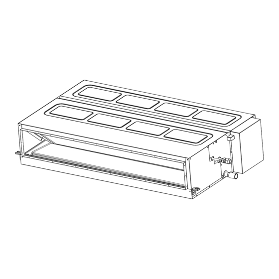
Page 8: Unit Description
Unit Description This heat-pump type air conditioning unit can consist of one outdoor unit and several indoor units. Detailed Do not have the indoor unit or outdoor unit configurations are stated in the corresponding exposed to water. All these parts are designed installation &... - Page 9 Models: 0.8~2.5 Models: 3.0~6.0 Fig. 3.1 In-the-Ceiling Indoor Unit...
-
Page 10: Automatic Defrosting
4. Before Operation Freeze Protection during Refrigeration When the outlet air temperature of indoor unit is excessively low, refrigeration may be automatically switched to air supply mode, in which the unit runs for The units that have been left unused for a long period of a period of time to avoid frosting on indoor heat time shall be electrified for more than 12 hours before exchanger. - Page 11 7. Cleaning of Filter Screen The operation of indoor unit is strictly prohibited without filter screen. Please turn off the main power supply before removing the filter screen (the previous operational function may occur). 8.1 If Trouble Still Remains 7.1 Removing Filter Screen If the trouble still remains even after checking the following, contact your contractor and inform 7.2 Cleaning Filter Screen...
- Page 12 Check whether the design pressure of machine is 4.15 MPa. The following tools are necessary for the installation & construction. Tool Tool Handsaw Spanner Phillips Screwdriver Charging Cylinder Gauge Manifold Vacuum Pump Cutter for Wires Refrigerant Gas Hose Megohmmeter Gas Leak Detector Leveller Copper Pipe Bender Water Pump...
- Page 13 Install the indoor unit as per national standard. Refer to the packing list in the end page of this manual for details of accessories. Please contact the dealer if the accessories are not delivered with machine.
- Page 14 Models: 0.8~2.5 Electric Box Service Access (≥450) Back Front Install suspension bolts as shown in Fig. 4.2. Top View Models: 3.0~6.0 Electric Box For Concrete Slab For Steel Beam Service Access (≥450) Insert 1. When the ceiling is 150 to 160mm (100 to150kg) not removable, please arrange a necessary...
-
Page 15: Installation Of Indoor Unit
4.3.2 Suspension Bolt and Pipe 4.3.3 Installation of Indoor Unit Connection Points Indoor unit is installed as shown in Fig. 4.4. Installation of Field-Supplied Parts (1) Indicate the location of suspension bolt, and the connection points of refrigerant pipe and drain Suspension Bolt 4-M10 or W3/8 pipe. -
Page 16: Air Duct Connection
4.3.5 Air Duct Connection (2) Installation of Indoor Unit Air duct is connected to indoor unit via canvas hose Place the left bracket on the nut and washer of to effectively isolate noise and vibration. Indoor unit suspension bolt as shown in the figure below. is designed with flange with hole connectible to air Make sure the left bracket is properly placed duct. -
Page 17: Piping Connection
As shown in Fig. 5.4, two spanners shall be used for 5.2 Piping Connection tightening the nut. (1) Piping connection points are shown in Figs. 5.1 and 5.2. Models 0.8~2.5 Drain Pipe Refrigerant Gas Tube For Drain Pump Refrigerant Liquid Tube (N.m) (mm) Drain Pipe... -
Page 18: Drain Pipe
Where the relative humidity of air inlet or Excessive and inadequate refrigerant is a ambient air exceeds 80%, an auxiliary drain pan leading cause of system anomaly. Please shall be fabricated at installation site and placed inject the right amount of refrigerant. under the indoor unit, as shown in Fig. - Page 19 Check the capacity of power source. The system can't be started if the supply ● voltage is excessively low. Turn OFF the main power switch to the indoor unit and the outdoor unit and wait for at least 3 minutes before electrical wiring work or a periodical check is performed.
- Page 20 7.3 Static Pressure Selection Wiring Static Pressure (Pa) RPIM-0.8~2.5HNAUNQ Plug Wording Static Pressure (Pa) RPIH-3.0~6.0HNAUNQ Plug Wording *: Factory default The plug printed with number "1" before delivery of above-noted indoor unit is inserted into the socket. To change the static pressure, insert the plug printed with number "2".
-
Page 21: Field Operation
10. Field Operation 10.1 Specifications of Field Connected Power CordMinimum Diameters of Field-Connected Wires and Power Cords Power Cord Signal Wire Power Supply Rated Current Models Specifications Specifications RPIL-0.8~1.0HNAUNQ 0.49A RPIL-1.3~1.5HNAUNQ 0.90A 0.76A RPIL-1.8~2.0HNAUNQ 220-240V ~ 50Hz 1.38A RPIL-2.3~2.5HNAUNQ 2.04A RPIL-3.0~4.0HNAUNQ 2.44A RPIL-5.0HNAUNQ... - Page 22 Safety reset (DSW7) No setup is needed All are set to OFF before delivery. (A) Positions of DIP Switches * In the case of applying high voltage to terminals 1 and 2 of TB2, the fuse on the PCB, is cut. In such a case, firstly connect the wiring to TB2, and then turn on NO.1 pin.
- Page 24 1110036 Qingdao Hisense Hitachi Air-conditioning Systems Co., Ltd. Add: 218, Qianwangang Road, Economic & Technical Development Zone, Qingdao, P.R. China http://www.hisense-vrf.com E-mail: export@hisensehitachi.com P01590Q 2018.08...
Need help?
Do you have a question about the RPIH-3.0HNAUNQ and is the answer not in the manual?
Questions and answers