Table of Contents
Advertisement
INSTALLATION AND MAINTENANCE MANUAL
HITACHI SPLIT AIR CONDITIONERS
Installation and Maintenance Manual
Models
< Indoor Units >
Heat Pump Type
RPIL
-1.0
-
UNE1NH*
RPIL
-1.5
UNE1NH*
RPIL
-2.0
-
UNE1NH*
RPIM
-3.0
UNE1NH
RPIH
-4.0
UNE1NH
RPIH
-
-5.0
UNE1NH
RPIH-6.0UNE1NH
RPIH-6.5UNE1NH
< Outdoor Units >
Heat Pump Type
RAS-1.0UNESNH1*
RAS-1.5UNESNH1*
RAS-2.0UNESNH1*
RAS-3.0UNESNH1
RAS-4.0UNESNH1
RAS-5.0UNESMH1
RAS-6.0UNESMH1
RAS-6.5UNESMH1
Cooling Only Type
RPIL
-1.0
TNE1NH*
RPIL
-1.5
TNE1NH*
RPIL
-2.0
-
TNE1NH*
RPIM
-3.0
TNE1NH*
RPIH
-4.0
TNE1NH*
RPIH
-
-5.0
TNE1NH*
RPIH-6.0TNE1NH*
RPIH-6.5TNE1NH*
Cooling Only Type
RAS-1.0TNESNH1*
RAS-1.5TNESNH1*
RAS-2.0TNESNH1*
RAS-3.0TNESNH1*
RAS-4.0TNESNH1*
RAS-5.0TNESMH1*
RAS-6.0TNESMH1*
RAS-6.5TNESMH1*
HPM2017009HA
Advertisement
Table of Contents

Related Manuals for Hitachi RPIL-1.0UNE1NH


Summary of Contents for Hitachi RPIL-1.0UNE1NH
- Page 1 INSTALLATION AND MAINTENANCE MANUAL HITACHI SPLIT AIR CONDITIONERS Installation and Maintenance Manual Models < Indoor Units > Heat Pump Type Cooling Only Type RPIL -1.0 UNE1NH* RPIL -1.0 TNE1NH* RPIL -1.5 UNE1NH* RPIL -1.5 TNE1NH* RPIL -2.0 UNE1NH* RPIL -2.0...
-
Page 2: Table Of Contents
Humidity 30%~80% ● The numbers in the model represent the cooling capacity in HP. For example, RPIL-1.0UNE1NH or RAS-1.0UNESNH1 represent 1.0HP. Alert Symbols: DANGER : The symbol refers to a hazard which can result in severe personal injury or death. -
Page 3: Caution Statements
CAUTION Statements We recommend that this air-conditioner is installed properly by qualified personnel in accordance with the installation instructions provided with the unit. Before installation, check if the voltage of the power supply at installation site is the same as the voltage shown on the nameplate. -
Page 4: Composition Of The Air-Conditioner
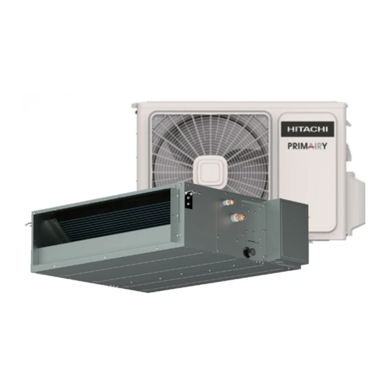
Composition of the Air-conditioner Indoor unit Air inlet Electric box Air outlet The conditioned air is blown out of the air-conditioner through this outlet. Outdoor unit 6.0/6.5HP 1.0/1.5/2.0/3.0/4.0/5.0HP Remote controller (Optional) You can control the air-conditioner with the wired controller or remote controller. It is used for power ON/OFF, setting the operation mode, temperature, fan speed and other functions. -
Page 5: Operation Manual
Operation manual Special remarks ● 3 minutes protection after compressor stop To protect compressor, it will be continue to be off for at least 3 minutes once it has stopped. ● 5 minutes protection Compressor must run for at least 5 minutes once operational. -
Page 6: Diagram Of Refrigerant Cycle & Wiring
Diagram of refrigerant cycle & Wiring 1. Refrigerant Flow Diagram INDOOR UNIT OUTDOOR UNIT Gas piping Compressor Accumulator Wide service valve 4-way valve Liquid piping Service valve Heating cycle Cooling cycle 2. Electrical Wiring Diagram Outdoor unit Indoor unit Indoor unit Outdoor unit Terminal Terminal... -
Page 7: Installation And Maintenance
Installation and Maintenance 1. Safety Notice WARNING · Installation should be performed by a qualified personnel. (Improper installation may cause water leakage, electrical shock or fire.) ·Install the unit according to the instructions given in this manual. (Incomplete installation may cause water leakage, electrical shock or fire). -
Page 8: The Tools And Instruments For Installation
Installation and Maintenance 2. The Tools and Instruments for Installation Number Tool Number Tool Standard screwdriver Knife or wire stripper Vacuum pump Leveller Charge hose Hammer Pipe bender Churn drill Adjustable wrench Tube expander Pipe cutter Inner hexagon spanner Cross head screw-driver Measuring tape 3. -
Page 9: Installation
Installation and Maintenance · Optimum air distribution is ensured. 3.2 Installation · The air path is not blocked. · Condensation can drain properly. 3.2.1 Suspension bolts · The ceiling is strong enough to bear the weight of the (1) Consider the pipe direction, wiring and maintenance indoor unit. - Page 10 Installation and Maintenance Air outlet Hanger bracket Suspension bolt Rack Indoor unit Double nuts and washers Fig. 3.6 3.2.4 The horizontal adjustment of the indoor unit (1) Make sure that the hanger bracket is fixed by the nuts and the washers. Air inlet (2) Adjust the height of the unit.
-
Page 11: The Piping Material
Installation and Maintenance 4. Refrigerant Pipe (2) As shown in Fig. 4.3, tighten the nuts with 2 spanners. DANGER Use the refrigerant according to outdoor nameplate. When carrying on the leakage check and test, do not mix in the oxygen, the acetylene and flammable and the reactive gas, these gases are quite dangerous, and may possibly cause explosion. -
Page 12: Drain Piping
Installation and Maintenance 5. Drain piping · Drain pipes passing indoors · Install the drain piping · Drain sockets. · Referring the figure below, insulate the drain socket Refrigerant pipes and drain hose using the included large sealing pad. Sealing material Sealing material Drain pipe connection hole (external straight pipe thread) -
Page 13: Electrical Wiring
Installation and Maintenance 6. Electrical Wiring 6.1 General Check CAUTION · When clamping the wiring, use the included clamping material as shown in the Fig.6.1 to prevent external pressure being exerted on the wiring connections and clamp firmly. · While performing wiring work, make sure the wiring is proper and does not cause the control box lid to stick up, then close the cover firmly. -
Page 14: Change Of Static Pressure
Installation and Maintenance Installation and Maintenance 6.2 Change of Static Pressure external static pressure of the indoor unit can be chosen. 6.2.1 For AC MOTOR type: You can change the static pressure by changing the fan motor terminal referring to the following Fig 6.2.1. Fan motor Low static pressure High static... -
Page 15: The Installation Of The Outdoor Unit
Installation and Maintenance 7. The Installation of the Outdoor Unit Pipe length L Indoor unit 7.1 Installation Sites Avoid Height difference H Outdoor unit Direct sunlight Aisle Or sideway Thick Oil fog Wet Or Uneven place Container With Flammable materials Near Heat Source/ventilation fan Add. -
Page 16: Refrigerant Piping
Installation and Maintenance 8. Refrigerant Piping The two refrigerant pipes (and electrical wire if local 8.1 Flaring with Pipe Expander codes permit) should be taped together with white Note: A good flare will have the following characteristics: armoring tape. The drain hose may also e included Inside surface is glossy and smooth. -
Page 17: Leak Test
Installation and Maintenance 9. Vacuuming and Test Run WARNING · Only after all the check points have been checked Air and moisture remaining in the refrigerant system the unit can be operated. have undesirable effects. (A) Check and make sure that the resistance of the Therefore, they must be removed completely with the Ω... -
Page 18: Electrical Installation
Installation and Maintenance 9.5 Electrical Installation ● Use an ELB (Electric Leakage Breaker). If not used, it may cause an electric shock or a fire. ● Do not operate the system until all the check points have been cleared. (A) Check to ensure that the insulation resistance is more than 2MΩ, by measuring the resistance between ground and the terminal of the electrical parts. - Page 19 They can take this product for environmental safe recycling. Specifications in this document are subject to change without notice, in order that Hitachi-Johnson Controls Air Conditioning, Inc. may bring the latest innovations to their customers.
Need help?
Do you have a question about the RPIL-1.0UNE1NH and is the answer not in the manual?
Questions and answers