Roger Technology BH30 Series Instructions And Recommendations For The Installer
Hide thumbs
Also See for BH30 Series:
- Instruction manual (73 pages) ,
- Instructions and recommendations for the installer (65 pages) ,
- User manual (12 pages)
Table of Contents
Advertisement
IS118 Rev.08 09/04/2020
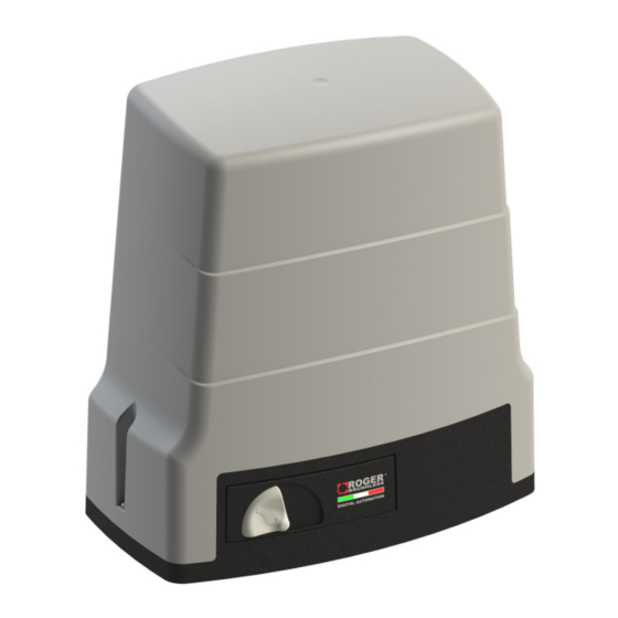
Serie BH30
Automazione per cancelli scorrevoli
Sliding gates automations
Automatisierung für Schiebetore
Automatisme pour portails coulissants
Automatismos para cancelas correderas
Automações para portões deslizantes
Istruzioni originali
ISTRUZIONI E AVVERTENZE PER L'INSTALLATORE
INSTRUCTIONS AND RECOMMENDATIONS FOR THE INSTALLER
ANWEISUNGEN UND HINWEISE FÜR DEN INSTALLATEUR
INSTRUCTIONS ET AVERTISSEMENTS POUR L'INSTALLATEUR
INSTRUCCIONES Y ADVERTENCIAS PARA EL INSTALADOR
INSTRUÇÕES E AVISOS PARA O INSTALADOR
Advertisement
Table of Contents

Related Manuals for Roger Technology BH30 Series


Summary of Contents for Roger Technology BH30 Series
- Page 1 IS118 Rev.08 09/04/2020 Serie BH30 Automazione per cancelli scorrevoli Sliding gates automations Automatisierung für Schiebetore Automatisme pour portails coulissants Automatismos para cancelas correderas Automações para portões deslizantes Istruzioni originali ISTRUZIONI E AVVERTENZE PER L’INSTALLATORE INSTRUCTIONS AND RECOMMENDATIONS FOR THE INSTALLER ANWEISUNGEN UND HINWEISE FÜR DEN INSTALLATEUR INSTRUCTIONS ET AVERTISSEMENTS POUR L’INSTALLATEUR INSTRUCCIONES Y ADVERTENCIAS PARA EL INSTALADOR...
-
Page 2: General Safety Precautions
WARNING: check that the existing structure fulfils the required resistance and stability specifications. ROGER TECHNOLOGY is not liable for failure to observe the good practices in the construction of fixtures to be moto- rised or for deformations that may occur during use. - Page 3 Keep out of the area of action of the motorised door or gate while it is moving. Never try to stop the motorised door or gate while it is moving as this may be dangerous. The motorised door or gate may be used by children aged 8 and above, by persons with diminished physical, sensory or mental capacity and by persons without the necessary experience and knowledge provided that they are supervi- sed or have received adequate instruction on using the device safely and to ensure that they understand the dangers involved in its operation.
-
Page 4: Useful Information
Symbol for the product disposal according to the WEEE directive. Product description ROGER TECHNOLOGY cannot be held responsible for any damage or injury due to improper use or any use other than the intended usage indicated in this manual. We recommend using only ROGER TECHNOLOGY accessories and control and safety devices. -
Page 5: Technical Data
Product label (example) The technical data shown in this manual do not replace those shown on the product label. ROGER TECHNOLOGY S.R.L. Via S. Botticelli 8 - 31021 The product label is applied to the motor, by opening the release handle (see figure). -
Page 6: Typical Installation
Typical installation DESCRIPTION RECOMMENDED CABLE BH30 Automation Power supply H07RN-F 3x1,5 mm2 double insulated cable External photocell F4ES/F4S - Transmitter Cable 3x0,5 mm (max 20 m) Power supply 24Vac 50Hz, 24Vdc External photocell F4ES/F4S - Receiver Cable 5x0,5 mm (max 20 m) Internal photocell F4ES/F4S - Transmitter Cable 3x0,5 mm (max 20 m) - Page 7 Preliminary checks and installation of the foundation plate PRELIMINARY CHECKS BEFORE INSTALLATION • Before proceeding with the installation, move the gate manually to check the mechanical conditions and if the movement is regular and friction-free. • Check that the gate is structurally sound and check that the gate leaf is stable. The gate may cause injury or damage to property in the event of derailing or falling to one side.
- Page 8 Fixing The Rack N.B.: The BH30 gearmotor may be used with racks with a teething module of 4. • Unlock the gearmotor (see User Guide) and move the gate into the open position. • Place the rack on the pinion, then fasten the entire length of the rack, sliding the gate to allow access to the fasteners. •...
-
Page 9: Electrical Connections
Electrical connections A switch or an omnipolar cut-off switch with a contact opening of at least 3 mm must be installed on the mains power line; put the cut-off switch in OFF position and disconnect any buffer batteries before performing any cleaning or maintenance operations. Ensure that an adequate residual current circuit breaker with a 0.03 A threshold and a suitable overcurrent cut-out are installed upstream the electrical installation in accordance with best practices and in compliance with applicable legislation. - Page 10 ROGER TECHNOLOGY is the exclusive proprietor holder of all rights regarding this publication. ROGER TECHNOLOGY reserves the right to implement any modifications without prior notification. Copying, scanning or any alterations to this document are prohibited without express prior authorised from by ROGER TECHNOLOGY.
- Page 11 Declares that the partly-completed machinery designed to be incorporated according to the corresponding instructions manual: Description of the device: 24 V DC automated system for sliding gates BH30 Series powered by the built-in control unit. Built-in control unit model: B70/1DC See the P.CODE field on the label applied to the product...
Need help?
Do you have a question about the BH30 Series and is the answer not in the manual?
Questions and answers
What code to I put into the motor to connect the remote controller