Table of Contents
Advertisement
Quick Links
Advertisement
Table of Contents

Subscribe to Our Youtube Channel
Related Manuals for Ohio Medical Push-To-Set PTS-ISU


Summary of Contents for Ohio Medical Push-To-Set PTS-ISU
- Page 1 Push-To-Set Intermittent Suction Unit (PTS-ISU) Service Manual High Flow High Vacuum ANSI MEDICAL VACUUM PTS-ISU - Analog PTS-ISU - Analog ANSI/ISO PTS-ISU - Analog 8700-0001-000, Rev4 (11/2010)
- Page 2 Ohio Medical or by Ohio Medical trained these agents. personnel. The Product must not be altered without the prior written approval of Ohio Medical’s Quality...
-
Page 3: Table Of Contents
Table of Contents 1/ Defi nitions and Abbreviations 7.5 Digital Gauge .............13 7.5.1 Removal of Batteries ........13 1.1 Defi nitions ............1 7.5.2 Inserting Batteries 1.2 Abbreviations ............1 8/ Service Checkout Procedure 2/ Scope 8.1 Setup ..............14 2.1 ANSI Vacuum Regulator ........2 8.2 Push-To-Set™... -
Page 4: 1/Defi Nitions And Abbreviations
1/Defi nitions and Abbreviations Defi nitions Note: A note provides additional information to clarify a point in the text. Important: An important statement is similar to a note but of greater emphasis. CAUTION: A CAUTION statement is used when the possibility of damage to the equip- ment exists. -
Page 5: 2/Scope
2/Scope 3/Description/Specifi cations This service manual contains service, maintenance 3.1 Description and parts information for the Push-To-SetTM Intermittent Suction Unit (PTS-ISU) WARNING: Do not use this device in the presence of fl ammable anesthetics. Static ANSI Vacuum Regulator charges may not dissipate and possible explosion hazard exists in the presence of Analog/Digital these agents. -
Page 6: Specifi Cations
3/Descriptions/Specifi cations (3.1 Description Continued) During use, as the fl ow requirement increases, the valve automatically opens to maintain suction at the preset level. Conversely, when the fl ow requirement decreases, the valve automatically closes to maintain suction at the preset level. The same mechanism compensates for changes in supply vacuum to automatically maintain the pre-set suction level. -
Page 7: 4/Operation
(minimum inside diameter is 6 Regulator mm[0.25 in]). Sleeve An Ohio Medical Hydrophobic Filter or Hydrophilic Filter and Overfl ow Safety Trap (OST) should be used between the collection container and regulator to prevent contamination of the regulator, wall outlet and pipeline system. -
Page 8: Mode Selection
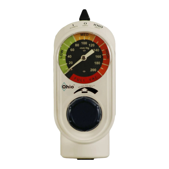
4/Operation 4.2 Mode Selection Figure 7 2. Push and rotate the suction control knob until the Figure 5 vacuum gauge indicates the required setting. IOIO (INT)- suction is intermittent (cycled “on” and “off”) and the suction level can be adjusted with the suction control knob when cycled “ON”. -
Page 9: Patient Setup
CAUTION: Unit failure due to cold fl ushing is been performed. not the responsibility of Ohio Medical and may 2. Move the mode selector switch to I (CONT) and invalidate the warranty. Failure to adequately push suction control knob. -
Page 10: Internal Component Cleaning
5/Cleaning 5.1.2 Internal Component Cleaning 5.2 Disinfection CAUTION: Cleaning the gauge may result in Should misuse occur resulting in accidental fl ooding damage. of the regulator, the regulator may be disinfected using Ethylene Oxide (ETO). After disinfection, follow 1. Refer to the Service - Disassembly and Assembly the service checkout procedures in Section 8. -
Page 11: 6/Troubleshooting
6/Troubleshooting Place the regulator in the vertical position and connect to a supply vacuum of 500 mmHg (66.7 kPa). Problem Possible Causes Remedy A. No gauge indication No supply vacuum Correct supply problems and no suction in any Kinked tube Straighten tube setting Poor connection... - Page 12 6/Troubleshooting Problem Possible Causes Remedy E. Suction level cannot Failure to push knob and Push and rotate to set vacuum level be adjusted rotate Regulator module is stuck in Rotate knob to un-stick full OFF or full ON position Regulator module See “Regulator module malfunction”...
- Page 13 6/Troubleshooting Problem Possible Causes Remedy K. Whistling/buzzing Cap-foam plug missing or Replace noise from inside the deteriorated/shrunk regulator Cap-foam plug pushed too Replace or install just fl ush with underside far into cap of cap Suction is delivered in Flow control valve is blocked Turn valve counter-clockwise until unit the CONT mode but or turned fully in...
-
Page 14: 7/Service - Disassembly And Assembly
Replace fi lters if needed. Replace or • Bubble leak tester lubricate o-rings if needed. • Stop watch or VACUTIMER (Ohio Medical P/N 7. If needed, remove the Timing Valve and the 6700-0438-800) Flow Control Valve with a fl athead screwdriver. •... -
Page 15: Assembly
7/Service - Disassembly and Assembly 7.2.2 Assembly b. Also insert one o-ring into the gauge orifi ce. Ensure o-ring is fl ush CAUTION: To prevent stripping the plastic case c. Attach the foam to the back of the gauge threads, place the manifold screw in the hole with the short leg at six o’clock. -
Page 16: Regulator Module
7/Service - Disassembly and Assembly 7.4 Timing and Flow Control Valves 7.3 Regulator Module Note: See SECTION 10.1 Illustrated Parts CAUTION: Do not over-tighten the Timing Valve or Flow Control Valve stems. Needle portion of CAUTION: Do not lubricate any internal valves may be damaged. -
Page 17: Setup
8/Set-Up 8.1 Set-up Important: Prior to venting port “A” of the Bubble Leak Tester to atmosphere (i.e. turning the supply 1. Verify there is 500 mmHg ± 10 mmHg (67 kPa ± regulator off), ensure the tubing from port “B” has 1.3 kPa) vacuum on the supply gauge. -
Page 18: Timing Cycle Adjustment
fi tting port still occluded. 5. Wait 20 seconds. Note: All Ohio Medical Analog Gauges are supplied with an accuracy of +/- 5% of full scale defl ection 6. If the regulator does not cycle “OFF” use a fl at- throughout their range. -
Page 19: Regulation Test
8/Set-Up 1. Connect the regulator fi tting port to the vacuum stop pin) in 5 seconds. calibration gauge with tubing. 6. If the regulator fails either the build-up or bleed- 2. Turn the mode selector switch to I (CONT). down test, replace the regulator module. 3. -
Page 20: General Maintenance Of Suction Equipment
9.2 Recommended Maintenance Schedule PTS-ISU should be kept in use or used on a rotating basis. Internal parts of unused equipment may tend Ohio Medical vacuum regulators function for decades. to deteriorate. They are proven to provide trouble-free service with minimum care. -
Page 21: Repair Policy
Have the equipment repaired by The torque range for installing adapters/probes and qualifi ed service personnel or by Ohio Medical. After fi ttings is 4.0 ft-lb (5.4 N-m) minimum to 10.0 ft-lb repair, perform the Service Checkout Procedure (13.6 N-m) maximum. -
Page 22: Illustrated Parts
Mode Selector Switch 8700-0016-500 Manifold Assy. 8700-0003-700 Manifold Screw 6700-0151-400 PTS-ISU Service Manual 8700-0001-000 For information on ANSI and/or ISO confi gurations, fi ttings, adapters, and accessories, refer to Ohio Medical’s Suction and Oxygen Therapy Product and Accessory Catalog. 8700-0001-000 Rev4... - Page 23 10/Illustrated Parts 8700-0001-000 Rev4...
- Page 24 1111 Lakeside Drive Gurnee, IL 60031 USA P: +1 866 549 6446 P: +1 847 855 0800 F: +1 847 855 6218 Ohio Medical Corporation Authorized Representative (OxygenCare Ltd.) 2 Holfeld Business Park Kilmacanogue Co Wicklow Ireland Tel: +353 1 2769700...
Need help?
Do you have a question about the Push-To-Set PTS-ISU and is the answer not in the manual?
Questions and answers