Vimar Eikon Instruction Handbook Manual
Bus device and access control system with smart cards
Hide thumbs
Also See for Eikon:
- Installer manual (15 pages) ,
- Manual (6 pages) ,
- Quick start manual (4 pages)
Chapters
Table of Contents

Subscribe to Our Youtube Channel
Related Manuals for Vimar Eikon


Summary of Contents for Vimar Eikon
- Page 1 Eikon Idea Plana 20471 16471 14471 Controllo accessi e gestione utenze via BUS mediante smart card Istruzioni BUS device and access control system with smart cards Instruction handbook...
- Page 2 IMPORTANTE. Gentile cliente, contrariamente a quanto riportato nel libretto istruzioni del prodotto nei paragrafi 8.1 (capi- tolo 8) e 9.3 (capitolo 9), la configurazione del lettore non può essere effettuata mediante il palmare /PDA. La programmazione dei dispositivi attraverso un apparecchio programmatore (PC) viene effettuata esclusivamente utilizzando la smart card per collegamento seriale 16474, seguen- do le procedure descritte nel paragrafo 9.4 (capitolo 9).
-
Page 3: Table Of Contents
ITALIANO INDICE 6. Funzionamento con smart card MASTER ... . . 35 1. Legenda ......... . 2 6.1 Inizializzazione lettore e codifica smart card MASTER . -
Page 4: Legenda
1. Legenda Led spento Operazioni da eseguire esclusivamente da personale qualificato Led acceso verde Operazioni che possono essere eseguite Led acceso giallo anche dall’utente Led acceso rosso 2 3 4 5 6 7 8 Dip-switch in posizione OFF Led lampeggiante verde, giallo o rosso 2 3 4 5 6 7 8 Dip-switch in posizione ON... -
Page 5: Installazione Sistema Via Bus
• Un sistema bus deve essere alimentato con 1 o 2 alimen- • Per i collegamenti utilizzare il doppino twistato e inguainato tatori e relativi choke (schema a pag. 4). VIMAR 01840 (2 x 0,5 mm , tensione nominale di esercizio 300/500 V); Il doppino distribuisce sia la tensione di •... - Page 6 492.18002 0A 0103 Made in Italy + – 29 V + – + – 492.1800 0A 0103 492.1842X 0A XXXX VIMAR - Marostica - Italy Eventuale secondo alimentatore 120-230 V~ 492.1800 0A 0103 50-60 Hz 29 V d.c. 01800 Alimentatore/Power supply 01842 I >...
-
Page 7: Caratteristiche E Funzioni Principali Dei Componenti Del Sistema
• Temperatura di funzionamento: –5 °C - +45 °C. • Con il dispositivo configurato senza l’ausilio del configu- ratore, non sarà possibile sfruttare tutte le funzionalità del sistema. • Antitamper (non attivo). Funzionalità utilizzabile solo nel caso di integrazione con il sistema antintrusione Vimar. Eikon Idea Plana 20471 16471 16471.B... - Page 8 SLAVE) e SLAVE (accesso solo dai punti abilitati). • Regolazione funzionamento relè monostabile o bistabile. • Gestione smart cards Vimar art. 16452. • Comando per arruolamento relè (procedura che può esse- re attivata in presenza di chiave abilitante e dalla pressione del tasto sul frontale).
- Page 9 Funzioni con configuratore e PDA (interfaccia IrDA) In questa modalità di funzionamento le smart card sono generate dal configuratore; tutte le informazioni sono gestite • Funzioni descritte nella modalità senza configuratore, attraverso un palmare e l’interfaccia IrDA. gestite via interfaccia software su PC e palmare. Le smart card, di qualsiasi tipo, create nella modalità...
-
Page 10: Dip Switch
3.2 - Dip switch Il lettore/programmatore smart card è dotato, sul retro, di dip-switch per la selezione degli indirizzi e per le modalità di funzionamento. Dip-switch Selezione indirizzi 1 2 3 1 2 3 4 5 6 7 4 5 6 7 1 2 3 4 5 6 7 1 2 3... -
Page 11: Smart Card 16452
3.3 - Smart card 16452 Area scrivibile per personaliz- zazione smart card Lettore in modalità “senza configuratore” Chip La “smart card” è una chiave elettronica in grado di memo- rizzare in 15 indirizzi distinti altrettanti codici generati casual- mente, al momento della programmazione, tra 4,29 miliardi di combinazioni per ciascuno di essi. -
Page 12: Attuatore A Relè
• Dati nominali relè: 3 A 30 V • Consumo tipico: 8 mA • Funzionamento in modalità monostabile • Trimmer per regolazione tempo di attivazione, da 0,25 a 10 s • Pulsante di configurazione Eikon Idea Plana 20472 16472 16472.B 14472 10 - ITALIANO ... -
Page 13: Alimentatore
3.5 - Alimentatore L’alimentatore è il dispositivo che consente di ottenere la ten- Caratteristiche tecniche sione a 29 V d.c., per l’alimentazione dell’impianto via BUS. • Tipo: switching • Tensione nominale di alimentazione 120-230 V~ ± 10% In esecuzione per montaggio su guida EN 50022, è disponi- bile in un’unica versione: •... -
Page 14: Bobina Di Disaccoppiamento (Choke)
In esecuzione per montaggio su guida EN 50022, viene for- nito in un’unica versione 01842: occupa 2 moduli da 17,5 mm, grigio RAL 7035 01842 CHOKE 29 V = 320 mA + – + – 492.1842X 0A XXXX VIMAR - Marostica - Italy 01842 12 - ITALIANO ... -
Page 15: Funzionamento
Funzionamento Modalità senza configuratore Il sistema funziona in due modalità: Il sistema funziona in due modi: Modalità senza configuratore 1. Controllo accessi e gestione utenze nel set- tore alberghiero tutte le operazioni sono gestite dal posizionamento dei dip switch e dalle smart card MASTER e/o smart card SLAVE - Funzionamento con smart card MASTER (2 livelli) - vedi cap. - Page 16 - Funzionamento con smart card MASTER (2 livelli) - Modalità con configuratore vedi cap. 6 a pag. 35. Qualsiasi operazione (inizializzazione, codifica, duplica- Il sistema funziona nel seguente modo: zione, cancellazione, cambio codice, sincronizzazione dei lettori), per essere eseguita, necessita di una smart Controllo accessi e gestione utenze card codificata MASTER.
-
Page 17: Controllo Accessi E Gestione Utenze Nel Settore Alberghiero
Controllo accessi e gestione utenze nel 4.1 Inizializzazione lettore e codifica settore alberghiero smart card MASTER Questa procedura consente di generare un codice MASTER nella memoria del lettore/programmatore da inizializzare e di Configurazione lettore smart card in copiarlo nelle smart card MASTER desiderate. modalità... - Page 18 4.1.3 4.1.6 6 7 8 Posizionare il dip-switch 2 in ON. Togliere la smart card. Il led si accende giallo. Il led torna verde in attesa di altre smart card MASTER da codificare. Per codificare ulteriori smart card MASTER ripetere le operazioni dal punto Card Card MASTER...
-
Page 19: Cambio Codice Lettore E Smart Card Master
4.2.2 4.2 Cambio codice lettore e smart Attendere che il led diventi rosso (dopo card MASTER circa 15 secondi), poi inserire la smart card MASTER. Questa procedura consente di assegnare un nuovo codi- ce MASTER alla memoria del lettore/programmatore e di Card Card copiarlo nelle smart card MASTER desiderate. - Page 20 4.2.6 4.2.4 Quando il led si spegne la smart card Togliere la smart card MASTER. MASTER è codificata. Il led diventa verde. Togliere la smart card e ripetere l’ope- Card Card MASTER MASTER razione dal punto 4.2.5 con altre smart Card Card card MASTER da codificare.
-
Page 21: Sincronizzazione Lettori Con Smart Card Master
4.3.2 4.3 Sincronizzazione lettori con smart Premere entro 15 secondi il tasto fronta- card MASTER le. Il led lampeggia verde. Attenzione! La procedura “Sincronizzazione Lettori con smart card Se il tasto non viene premuto entro MASTER” consente di far funzionare più lettori utilizzando la 15 secondi, il led diventa verde e il stessa smart card MASTER e lo stesso codice MASTER. - Page 22 4.3.4 Sincronizzazione di un lettore già inizializzato Il led si spegne per segnalare che il codi- ce della smart card è stato copiato e il lettore/programmatore è sincronizzato. 4.3.7 6 7 8 Posizionare il dip-switch 2 del lettore da sincronizzare in ON. Il led si accende giallo.
- Page 23 4.3.9 4.3.11 Inserire nel lettore da sincronizzare la Togliere la smart card MASTER. smart card MASTER. Il led lampeggia verde. Card Card MASTER MASTER 4.3.12 Se il led lampeggia rosso, la smart card Inserire nel lettore da sincronizzare una non è riconosciuta. smart card MASTER già...
-
Page 24: Inizializzazione Lettore E Codifica O Ricodifica Smart Card Slave
4.3.14 4.4 Inizializzazione lettore e codifica o Togliere la smart card. ricodifica smart card SLAVE Il led torna verde. Questa procedura consente di generare un codice SLAVE nella memoria del lettore/programmatore da inizializzare e di copiarlo nelle smart card desiderate. Ogni volta che si entra nella procedura “Inizializzazione lettore e codifica smart card SLAVE”, il codice generato è... - Page 25 4.4.2 4.4.4 Ripremere il tasto frontale. Il led diventa Se la smart card MASTER è riconosciuta, giallo. il led si spegne. Card Card MASTER MASTER 4.4.5 4.4.3 Togliere la smart card MASTER. Attendere che il led diventi rosso (dopo Il led diventa verde in attesa di una smart circa 15 secondi), poi inserire la smart card SLAVE da codificare.
-
Page 26: Controllo Accessi E Gestione Utenze Nei Settori Residenziale E
4.4.7 Controllo accessi e gestione utenze nei Quando il led si spegne la smart card settori residenziale e terziario SLAVE è codificata o ricodificata. Funzionamento senza smart card MASTER 4.4.8 Togliere la smart card SLAVE. 5.1 Inizializzazione lettore e codifica Il led torna verde in attesa di altre smart smart card SLAVE card SLAVE da codificare o ricodificare. - Page 27 4 5 6 7 8 5.1.6 5.1.3 1 2 3 4 5 6 7 Quando il led si spegne, la smart card è Selezionare l’indirizzo desiderato (vedi tabella “Selezione indirizzi” a pagina 8). codificata. Nell’esempio è stato utilizzato l’indirizzo 5.1.7 Togliere la smart card.
-
Page 28: Cambio Codice Lettore E Smart Card Slave
Se la smart card non è riconosciuta, il led 5.2 Cambio codice lettore e smart lampeggia rosso. Togliere la smart card card SLAVE errata e inserire quella corretta. Questa procedura consente di cambiare il codice assegnato all’indirizzo del lettore/programmatore e di memorizzarlo sulla smart card. - Page 29 5.2.5 5.2.7 Inserire una smart card da codificare. Togliere la smart card. Il led ritorna verde in attesa di altre smart card da codificare. Per codificare ulteriori smart card ripetere le operazioni dal punto 5.2.5. 5.2.8 2 3 4 5 6 7 8 5.2.6 Per uscire dalla procedura, posizionare il Quando il led si spegne, la smart card è...
-
Page 30: Sincronizzazione Lettori
5.3.2 5.3 Sincronizzazione lettori Premere entro 15 secondi il tasto fronta- le. Il led lampeggia verde. Attenzione! La procedura “Sincronizzazione Lettori” consente di far fun- Se il tasto non viene premuto entro zionare più lettori utilizzando la stessa smart card, lo stesso 15 secondi, il led verde si accende e il indirizzo e lo stesso codice. - Page 31 Sincronizzazione di un lettore già inizializzato 5.3.4 Quando il led si spegne il codice della smart card è stato copiato e il lettore è 5.3.7 2 3 4 5 6 7 8 sincronizzato. Posizionare il dip-switch 1 del lettore da sincronizzare in ON.
- Page 32 5.3.9 5.3.12 Inserire nel lettore una smart card codi- Togliere la smart card. ficata dal lettore stesso per abilitare la Il led lampeggia verde in attesa di una continuazione della procedura. smart card sincronizzante. Card già Card già codi cata codi cata 5.3.13 5.3.10...
-
Page 33: Duplicazione Smart Card Slave
5.3.15 5.4 Duplicazione smart card SLAVE Togliere la smart card. Il led diventa verde. Questa procedura consente, in qualsiasi momento, di dupli- care smart card SLAVE. Nota: Per duplicare smart card abilitate a più lettori/pro- grammatori, la procedura deve essere eseguita su ciascun lettore/programmatore. - Page 34 5.4.3 5.4.5 Attendere che il led diventi rosso (circa 15 Togliere la smart card. secondi), poi inserire la smart card codifi- Il led diventa verde in attesa di una smart cata che si desidera duplicare. card da codificare come copia. Se la smart card MASTER non viene inserita entro 15 secondi il led si spegne ed il Card già...
-
Page 35: Cancellazione Smart Card Slave
5.4.8 5.5 Cancellazione smart card SLAVE Togliere la smart card. Il led diventa verde in attesa di altre smart card da codificare come copia. Questa procedura consente di disabilitare qualsiasi smart card. Per codificare ulteriori smart card come copia ripetere le operazioni dal punto Attenzione! È... - Page 36 5.5.3 5.5.5 Premere ancora il tasto frontale. Il led Se la smart card è riconosciuta, il led si diventa rosso. spegne. 5.5.6 Togliere la smart card. 5.5.4 Il led diventa verde in attesa di una smart Inserire una smart card codificata per card da cancellare.
-
Page 37: Funzionamento Con Smart Card Master
5.5.8 Controllo accessi e gestione utenze nei Quando il led si spegne la smart card è settori residenziale e terziario cancellata. Funzionamento con smart card MASTER 5.5.9 Togliere la smart card. • Qualsiasi operazione (inizializzazione, codifica, duplicazio- Il led diventa verde in attesa di altre smart ne, cancellazione, cambio codice, sincronizzazione dei card da cancellare. -
Page 38: Inizializzazione Lettore E Codifica Smart Card Master
4 5 6 7 8 6.1.3 1 2 3 4 5 6 7 6.1 Inizializzazione lettore e codifica Selezionare l’indirizzo desiderato (vedi smart card MASTER tabella “Selezione indirizzi” a pagina 8). Nell’esempio è stato utilizzato l’indirizzo Questa procedura consente di generare un codice MASTER, associarlo all’indirizzo selezionato dai dip-switch del lettore/ programmatore da inizializzare e di copiarlo nelle smart card MASTER desiderate. -
Page 39: Cambio Codice Lettore E Smart Card Master
6.1.6 6.2 Cambio codice lettore e smart Quando il led si spegne, la smart card card MASTER MASTER è codificata. Questa procedura consente di cambiare il codice MASTER Card Card MASTER MASTER assegnato all’indirizzo del lettore/programmatore e di memorizzarlo sulla smart card. 6.1.7 6.2.1 6 7 8... - Page 40 Se il led lampeggia rosso, la smart card 6.2.5 non è stata riconosciuta. Inserire la smart card da ricodificare Estrarre la smart card e inserire la smart come MASTER. card MASTER corretta. Attenzione! Eventuali ulteriori smart card con il pre- Card MASTER cedente codice devono essere ricodi-...
-
Page 41: Inizializzazione Lettore E Codifica O Ricodifica Smart Card Slave
6.2.7 6.3 Inizializzazione lettore e codifica Togliere la smart card. o ricodifica smart card SLAVE Il led torna verde in attesa di altre smart card MASTER da ricodificare. Questa procedura consente di generare un codice SLAVE, Per ricodificare ulteriori smart card associarlo all’indirizzo selezionato dai dip-switch del lettore/ MASTER ripetere le operazioni dal punto programmatore da inizializzare e di copiarlo nelle smart card... - Page 42 6.3.2 6.3.4 Quando il led diventa rosso (dopo circa Togliere la smart card MASTER. 15 secondi), inserire la smart card Il led ritorna verde in attesa di una smart MASTER per abilitare la procedura. card SLAVE da codificare. Card Card Card Card MASTER...
-
Page 43: Sincronizzazione Lettori Con Smart Card Master
6.3.6 6.4 Sincronizzazione lettori con smart Quando il led si spegne la smart card card MASTER SLAVE è codificata. La procedura “Sincronizzazione Lettori con smart card Card Card MASTER” consente di far funzionare più lettori utilizzando la SLAVE SLAVE stessa smart card MASTER, lo stesso indirizzo e lo stesso codice MASTER. - Page 44 6.4.2 6.4.4 Premere entro 15 secondi il tasto fronta- Quando il led si spegne il codice della le. Il led lampeggia verde. smart card è stato copiato e il lettore è sincronizzato. Attenzione! Se il tasto non viene premuto entro 15 secondi, il led diventa verde e il sistema si predispone per la procedura “Inizializzazione lettore e codifica smart...
- Page 45 Sincronizzazione di un lettore già inizializzato 6.4.9 Inserire nel lettore una smart card MASTER codificata dal lettore stesso per 6.4.7 6 7 8 abilitare la continuazione della procedura. Posizionare il dip-switch 2 del lettore da sincronizzare in ON. Card Card Il led si accende giallo.
- Page 46 6.4.14 6.4.11 Togliere la smart card. Togliere la smart card MASTER. Il led diventa verde. Il led lampeggia verde in attesa di una smart card sincronizzante. 6.4.12 6.4.15 6 7 8 Inserire una smart card codificata dal let- Per uscire dalla procedura posizionare il tore sincronizzante.
-
Page 47: Sincronizzazione Lettori Con Smart Card Slave
6.5.1 2 3 4 5 6 7 8 6.5 Sincronizzazione lettori con smart Posizionare il dip-switch 1 del lettore da card SLAVE sincronizzare in ON. Il led si accende giallo. Questa procedura consente di far funzionare più lettori utilizzando la stessa smart card SLAVE, lo stesso indirizzo e lo stesso codice SLAVE. - Page 48 6.5.5 6.5.3 Togliere la smart card MASTER. Inserire nel lettore una smart card Il led lampeggia verde in attesa di una MASTER codificata dal lettore stesso per smart card SLAVE codificata dal lettore abilitare la continuazione della procedura. sincronizzante. Card Card MASTER MASTER...
-
Page 49: Duplicazione Smart Card Slave
6.5.8 6.6 Duplicazione smart card SLAVE Togliere la smart card. Il led diventa verde. Nota: Per duplicare smart card abilitate a più lettori/pro- grammatori, la procedura deve essere eseguita su ciascun lettore/programmatore. 6.6.1 Premere il tasto frontale. Il led lampeggia rosso-spento-verde a 6.5.9 2 3 4 5 6 7 8 intermittenza. - Page 50 6.6.3 6.6.5 Attendere che il led diventi rosso (circa Togliere la smart card MASTER. 15 secondi), poi inserire una smart card Il led diventa verde in attesa di una smart MASTER per abilitare la procedura. card SLAVE da duplicare. Se la smart card non viene inserita entro 15 secondi il led si spegne e il dispositivo esce Card Card...
-
Page 51: Cancellazione Smart Card Slave
6.6.8 6.7 Cancellazione smart card SLAVE Togliere la smart card SLAVE. Il led diventa verde in attesa di altre smart card SLAVE da duplicare. Questa procedura consente di disabilitare smart card Per duplicare ulteriori smart card ripetere SLAVE o smart card MASTER con codice SLAVE. I codici le operazioni dal punto 6.6.6. - Page 52 Se il led lampeggia rosso, la smart card 6.7.2 Premere il tasto frontale. Il led diventa MASTER non è riconosciuta. giallo. Togliere la smart card errata e inserire quella corretta. 6.7.5 6.7.3 Se la smart card è riconosciuta, il led si Premere ancora il tasto frontale.
- Page 53 6.7.7 6.7.10 Inserire la smart card SLAVE da can- Per uscire dalla procedura, premere il cellare. pulsante frontale. Il led si spegne. Il dispositivo resta in attesa della smart card da cancellare per circa 15 secondi, dopo di che esce dalla procedura. Card Card SLAVE...
-
Page 54: Associazione Del Lettore Al Relè
7.1.2 Associazione del lettore al relè Ripremere il tasto frontale. Il led diventa giallo. 7.1 Associazione al relè Questa procedura consente di associare un relè al lettore. Il relè associato verrà poi attivato soltanto se il lettore ricono- 7.1.3 scerà la chiave. Attendere che il led diventi rosso (circa 15 secondi), poi inserire una smart card MASTER per abilitare la procedura. - Page 55 Nota: Durante la configurazione il led 7.1.4 Se la smart card è riconosciuta, il led si del lettore continua a lampeggiare alter- spegne. Non estrarre la smart card. nativamente rosso-verde e si spegne a configurazione ultimata. Card Card Card Card MASTER MASTER MASTER...
-
Page 56: Lettore In Modalità Senza Configuratore
8.1.2 Lettore in modalità senza configuratore Ripremere il tasto frontale. Il led diventa giallo. 8.1 Attivazione porta IrDA (lettore in modalità “senza configuratore”) Questa procedura consente la comunicazione tra palmare e lettore. 8.1.3 Attendere che il led diventi rosso, poi 8.1.1 inserire una smart card MASTER per abi- Premere il tasto frontale. - Page 57 Se il led lampeggia rosso, la smart card 8.1.6 non è riconosciuta. Ripremere il tasto frontale. Togliere la smart card errata e inserire Il led diventa verde. quella corretta. La porta a infrarosso è attivata. 8.1.4 Se la smart card è riconosciuta, il led si spegne.
-
Page 58: Lettore In Modalità Con Configuratore
8.1.8 Lettore in modalità con configuratore Effettuare le operazioni con il palmare. Per le istruzioni, vedere il manuale conte- nuto nel CD-ROM. 9.1 Predisposizione del lettore in modalità di funzionamento con Auto-generated:Invia Dati configuratore e PDA INVIO DATI A LETTORE: In questa modalità... - Page 59 9.1.1 9.1.6 Alimentare il lettore. Associare il relè effettuando le operazioni descritte nel capitolo 7.1 Associazione del relè (pag. 52) Nota: Questa operazione può essere effettua- 9.1.2 1 2 3 4 5 6 7 ta anche successivamente. Posizionare il dip-switch 8 in OFF. 9.1.3 9.1.7 1 2 3...
-
Page 60: Associazione Al Relè (Lettore In Modalità "Con Configuratore")
9.2.3 9.2 Associazione al relè (lettore in Attendere che il led diventi rosso (circa modalità “con configuratore”) 15 secondi), poi inserire la smart card MASTER per abilitare la procedura. Questa procedura consente di associare un relè al lettore. Se la smart card non viene inserita entro 15 Il relè... - Page 61 9.2.5 Se il relè non viene configurato esce Premere il pulsante del relè da associare automaticamente dalla modalità di confi- (Il relè si contraddistingue dal simbolo gurazione dopo circa 1,5 minuti, oppure dell’attuatore evidenziato in figura). togliendo l’alimentazione al relè stesso. Il led del relè...
-
Page 62: Attivazione Porta Irda (Lettore In Modalità "Con Configuratore")
9.3.2 9.3 Attivazione porta IrDA (lettore in Ripremere il tasto frontale. Il led diventa modalità “con configuratore”) giallo Questa procedura consente la comunicazione tra palmare e lettore. Nota: La prima attivazione della porta IrDA deve essere effettuata con il lettore in modalità senza configura- tore seguendo la procedura descritta nel capitolo 8.1 9.3.3 “Attivazione porta IrDA (lettore in modalità... - Page 63 9.3.4 9.3.7 Se la smart card è riconosciuta il led lam- Effettuare le operazioni di programmazio- peggia alternato rosso-verde. ne o scambio dati con il palmare. Attendere circa 5 secondi Le funzioni sono descritte a pag. 6. Card Card Per le istruzioni, vedere il manuale conte- MASTER MASTER nuto nel CD-ROM.
-
Page 64: Collegamento Attraverso Smart Card Per Collegamento Seriale 16474
9.4.1 9.4 Collegamento attraverso smart Attivare la porta IrDA nel lettore/program- card per collegamento seriale matore a smart card come descritto nei 16474 punti 8.1 o 9.3 (secondo la modalità del lettore) In alternativa al collegamento attraverso interfaccia IrDA è possibile usare la smart card per collegamento seriale 16474 per la comunicazione tra lettore/programmatore 9.4.2 smart card e dispositivo programmatore (PC o PDA). - Page 65 9.4.4 9.4.6 Procedere con le normali operazioni di Premere il tasto frontale per disattivare la configurazione. porta a infrarossi. Il led si spegne. Per le istruzioni, vedere il manuale conte- nuto nel CD-ROM. 9.4.5 Al termine delle operazioni estrarre il con- nettore piatto dal lettore.
- Page 67 ENGLISH CONTENTS 1. Key ....................2 6. Operation with a MASTER smart card ........35 2. Installation of the BUS system ............3 6.1 Initialising the reader and programming MASTER smart cards 36 3. Principal functions and characteristics of the system components ... 5 6.2 Changing the reader and MASTER smart card codes ..
-
Page 68: Key
1. Key LED off Operations to be performed exclusively by a qualified technician LED illuminated green Operations that can also be carried out by LED illuminated yellow the user LED illuminated red 2 3 4 5 6 7 8 Dip-switch in OFF position LED blinking green, yellow or red 2 3 4 5 6 7 8... -
Page 69: Installation Of The Bus System
2. Installation of the BUS system • The bus system can be powered by 1 or 2 power sup- • For the connections, use a VIMAR 01840 insulated twisted plies, each with its choke (diagram on pg. 4). pair (2 x 0.5 mm , rated voltage 300/500 V);... - Page 70 492.18002 0A 0103 Made in Italy + – 29 V + – + – 492.1800 0A 0103 492.1842X 0A XXXX VIMAR - Marostica - Italy Additional power supply 120-230 V~ 492.1800 0A 0103 50-60 Hz 29 V d.c. 01800 Alimentatore/Power supply 01842 I >...
-
Page 71: Principal Functions And Characteristics Of The System Components
• In the operating mode without a configurator, not all the • typical current draw: 16 mA system functions will be available. • Operating temperature: –5 °C - +45 °C. • Antitamper (not used). Function enabled only in conjunc- tion with the Vimar intrusion-protection system. Eikon Idea Plana 20471 16471 16471.B... - Page 72 SLAVE smart cards) and SLAVE (can only access the enabled points). • Choice of monostable or bistable relay operation. • Support for Vimar 16452. • Command for associating a relay (procedure invoked Key: using a master card and pressing the front button).
- Page 73 Functions in the operating mode with a configurator and • Configuration of smart card access parameters. PDA (IrDA interface) • Ability to store up to 12 different smart cards in memory. • All the same functions described previously for operation without a configurator mode, but controlled via a software interface on a PC or handheld.
-
Page 74: Dip Switch
Dip-switches 3.2 - The reader/programmer is provided with dip- switches at the rear for selecting the addresses and operating modes. Dip-switches Address selection 1 2 3 1 2 3 4 5 6 7 4 5 6 7 1 2 3 4 5 6 7 1 2 3 4 5 6 7... -
Page 75: Smart Card 16452
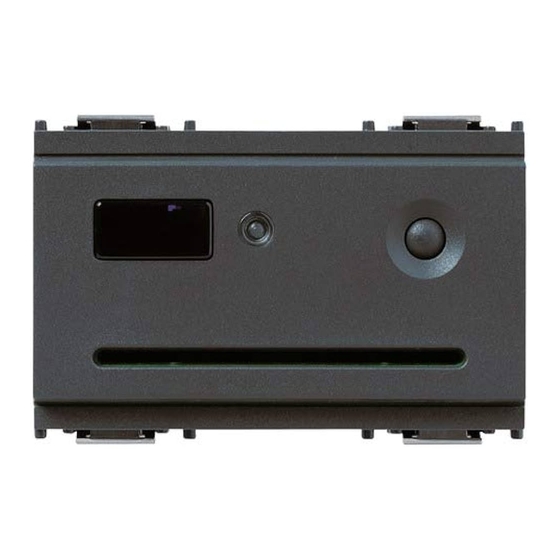
3.3 - Smart card 16452 Writable area for smart card personalisation Reader in “without configurator” mode Chip The “smart card” is an electronic key with 15 distinct mem- ory addresses, in which it can store 15 different codes that are randomly generated at the time of programming, out of a total of 4.29 billion possible combinations. -
Page 76: Relay Actuator
• Relay characteristics: 3 A 30 V • Typical current draw: 8 mA • Operation in monostable mode • Trimmer for adjusting relay activation time, between 0.25 and 10 seconds • Configuration button Eikon Idea Plana 20472 16472 16472.B 14472... -
Page 77: Power Supply
3.5 - Power supply The power supply furnishes the 29 V dc voltage for powering Technical specifications the BUS system. • Type: switching • Rated supply voltage (Vn): 120-230 V~ ±10% The construction for EN 50022 guide mount is available in a single version: •... -
Page 78: Decoupling Coil (Choke)
The construction for EN 50022 guide mount is available in a single version: 01842: occupies two 17.5 mm modules, grey RAL 7035 01842 CHOKE 29 V = 320 mA + – + – 492.1842X 0A XXXX VIMAR - Marostica - Italy 01842 12 - ENGLISH... -
Page 79: Operation
Operation Operation without a configurator The system has two operating modes: The system can function in two ways: Operation without a configurator 1. Device and access control in the hotel sec- tor: All functions are controlled by means of the dip-switch set- tings and using the MASTER and/or SLAVE smart cards. - Page 80 - Operation with a MASTER smart card (2 levels) - see Operation with a configurator ch. 6, pg. 35. A smart card programmed as a MASTER is needed to per- The system functions as follows: form any operation (initialising, programming, duplicating, cancelling, changing the code, synchronising readers).
-
Page 81: Smart Card Reader Operation Without A Configurator
Device and access control in the hotel 4.1 Initialising the reader and pro- sector: gramming MASTER smart cards This procedure generates a MASTER code in the memory of the reader/programmer being initialised, and copies it to the Smart car reader operation without a desired MASTER smart cards. - Page 82 4.1.3 4.1.6 6 7 8 Place dip-switch 2 in the ON position. Remove the smart card. The LED lights up yellow. The LED turns green again, waiting for other MASTER smart cards to program. To program additional MASTER smart cards, repeat the procedure from MASTER MASTER card...
-
Page 83: Changing The Reader And Master Smart Card Codes
4.2.2 4.2 Changing the reader and smart Wait for the LED to turn red (after about card codes 15 seconds), then insert the MASTER smart card. This procedure assigns a new MASTER code to the mem- ory of the reader/programmer and copies it to the desired MASTER MASTER MASTER smart cards. - Page 84 4.2.6 4.2.4 When the LED turns off, the MASTER Remove the MASTER smart card. smart card has been programmed. The LED turns green. Remove the smart card and repeat the MASTER MASTER card card operation from step 4.2.5 with any other MASTER MASTER MASTER smart cards to be programmed.
-
Page 85: Synchronising Readers With Master Smart Cards
4.3.2 4.3 Synchronising readers with Press the front button within 15 sec- MASTER smart cards onds. The LED turns green. Warning! The “Synchronise readers with MASTER smart card” pro- If the button is not pressed within 15 cedure programs several readers to work with the same seconds, the LED turns green and the system switches to the “Initialise reader MASTER smart card, the same address and the same... - Page 86 Synchronising an already-initialised reader 4.3.4 The LED switches off to signal that the smart card code has been copied, and the reader/programmer synchronised. 4.3.7 6 7 8 Place dip-switch 2, on the reader being synchronised, in the ON position. The LED lights up yellow. 4.3.5 Remove the MASTER smart card.
- Page 87 4.3.9 4.3.11 Insert the MASTER smart card into the Remove the MASTER smart card. reader being synchronised. The LED blinks green. MASTER MASTER card card 4.3.12 If the LED blinks red it means the key Insert a MASTER smart card, already was not recognised.
-
Page 88: Initialising The Reader And Programming Or Reprogramming Slave Smart Cards
4.3.14 4.4 Initialising the reader and pro- Remove the smart card. gramming or reprogramming The LED turns green again. SLAVE smart cards This procedure generates a SLAVE code in the memory of the reader/programmer being initialised, and copies it to the desired smart cards. - Page 89 4.4.2 4.4.4 Press the front button again. The LED If the MASTER smart card is recognised, turns yellow. the LED switches off. MASTER MASTER card card 4.4.5 4.4.3 Remove the MASTER smart card. Wait for the LED to turn red (after about The LED turns green, waiting for a SLAVE 15 seconds), then insert the MASTER smart card to program.
-
Page 90: Device And Access Control In The Residential And Services Sectors
4.4.7 Device and access control in the resi- When the LED turns off, the SLAVE smart dential and services sectors: card has been programmed or repro- grammed. Operation without a MASTER smart card 4.4.8 Remove the SLAVE smart card. 5.1 Initialising the reader and program- The LED turns green, waiting for other ming SLAVE smart cards SLAVE smart cards to program or repro-... - Page 91 4 5 6 7 8 5.1.6 5.1.3 1 2 3 4 5 6 7 When the LED turns off, the smart card Select the desired address (see “Address selection” table on page 8). has been programmed. In the example, address A was used. 5.1.7 Remove the smart card.
-
Page 92: Changing The Reader And Smart Slave Card Codes
If the smart card is not recognised, the 5.2 Reprogramming the reader code LED blinks red. Remove the incorrect and SLAVE smart cards smart card and insert the correct one. This procedure changes the code assigned to the address of the reader/programmer, and saves it to the smart card. 5.2.3 5.2.1 2 3 4 5 6 7 8... - Page 93 5.2.5 5.2.7 Insert a smart card to program. Remove the smart card. The LED turns green again, waiting for other smart cards to program. To program additional smart cards, repeat the procedure from step 5.2.5. 5.2.8 2 3 4 5 6 7 8 5.2.6 To exit the procedure, place dip-switch 1 in When the LED turns off, the smart card...
-
Page 94: Synchronising Readers
5.3.2 5.3 Synchronising readers Press the front button within 15 sec- onds. The LED blinks green Warning! The “Synchronising Readers” procedure configures several If the button is not pressed within 15 different readers to work using the same smart card, the seconds, the LED turns green and the same address and the same code. - Page 95 Synchronising an already-initialised reader 5.3.4 The LED switches off to signal that the smart card code has been copied, and 5.3.7 2 3 4 5 6 7 8 the reader synchronised. Place dip-switch 1, on the reader being synchronised, in the ON position. The LED lights up yellow.
- Page 96 5.3.9 5.3.12 Insert into the reader a smart card pro- Remove the smart card. grammed by that same reader, to enable The LED blinks green, waiting for a syn- continuation of the procedure. chronising smart card. Card Card already already programmed programmed 5.3.13...
-
Page 97: Duplicating Slave Smart Cards
5.3.15 5.4 Duplicating SLAVE smart cards Remove the smart card. The LED turns green again. This procedure can be used to make copies of SLAVE smart cards at any time. Note: When duplicating smart cards that are enabled for several readers/programmers, the procedure must be repeated on each reader/programmer. - Page 98 5.4.3 5.4.5 Wait for the LED to turn red (after about Remove the smart card. 15 seconds), then insert the programmed The LED turns green, waiting for the smart card to be duplicated. smart card to program as a duplicate. If the MASTER smart card is not inserted Card Card...
-
Page 99: Cancelling Slave Smart Cards
5.4.8 5.5 Cancelling SLAVE smart cards Remove the smart card. The LED turns green, waiting for addition- al smart cards to program as duplicates. This procedure is used for cancelling smart cards. To program additional duplicate smart Warning! At least one smart card must be left enabled, in cards, repeat the procedure from step order to continue accessing the system procedures. - Page 100 5.5.3 5.5.5 Press the front button again. The LED If the smart card is recognised, the LED turns red. switches off. 5.5.6 Remove the smart card. 5.5.4 The LED turns green, waiting for a smart Insert a programmed smart card to card to cancel.
-
Page 101: Operation With A Master Smart Card
5.5.8 Device and access control in the resi- When the LED turns off, the smart card dential and services sectors: has been cancelled. Operation with a MASTER smart card 5.5.9 • a MASTER smart card is required to perform any opera- Remove the smart card. -
Page 102: Initialising The Reader And Programming Master Smart Cards
4 5 6 7 8 6.1.3 1 2 3 4 5 6 7 6.1 Initialising the reader and pro- Select the desired address (see “Address gramming MASTER smart cards selection” table on page 8). In the example, address A was used. This procedure generates a MASTER code, associates it with the address selected by the dip-switches on the read- er/programmer being initialised, and copies it to the desired... -
Page 103: Changing The Reader And Master Smart Card Codes
6.1.6 6.2 Changing the reader and MASTER When the LED turns off, the MASTER smart card codes smart card has been programmed. This procedure changes the MASTER code assigned to MASTER MASTER card card the address of the reader/programmer, and saves it to the smart card. - Page 104 If the LED blinks red it means the smart 6.2.5 card was not recognised. Insert the smart card to be programmed Remove the smart card and insert the as a MASTER. correct MASTER smart card. Warning! Any additional smart cards containing the MASTER MASTER old code must be reprogrammed with...
-
Page 105: Initialising The Reader And Programming Or Reprogramming Slave Smart Cards
6.2.7 6.3 Initialising the reader and pro- Remove the smart card, the LED turns gramming or reprogramming green again, waiting for other smart cards SLAVE smart cards to reprogram. To reprogram additional MASTER smart This procedure generates a SLAVE code, associates it with cards, repeat the procedure from step the address selected by the dip-switches on the reader/ 6.2.5. - Page 106 6.3.2 6.3.4 When the LED turns red (after about When the LED turns red (after about 15 seconds), insert the currently active 15 seconds), insert the currently active MASTER smart card to enable the pro- MASTER smart card to enable the pro- cedure.
-
Page 107: Synchronising Readers With Master Smart Cards
6.3.6 6.4 Synchronising readers with When the LED turns off, the SLAVE smart MASTER smart cards card has been programmed. The “Synchronise Readers with MASTER smart card” pro- SLAVE SLAVE card cedure allows several readers to operate using the same card MASTER smart card and the same MASTER code. - Page 108 6.4.2 6.4.4 Press the front button within 15 sec- The LED switches off to signal that the onds. The LED blinks green smart card code has been copied, and the reader synchronised. Warning! If the button is not pressed within 15 seconds, the LED turns green and the system switches to the “Initialise reader and program MASTER smart cards”...
- Page 109 Synchronising an already-initialised reader 6.4.9 Insert into the reader a MASTER smart card programmed by that same reader, 6.4.7 6 7 8 to enable continuation of the procedure. Place dip-switch 2 on the reader being synchronised in the ON position. MASTER MASTER The LED lights up yellow.
- Page 110 6.4.14 6.4.11 Remove the smart card. Remove the MASTER smart card. The LED turns green. The LED blinks green, waiting for a syn- chronising smart card. 6.4.12 6.4.15 6 7 8 Insert a smart card programmed by the To exit the procedure, place dip-switch 2 synchronising reader.
-
Page 111: Synchronising Readers With Slave Smart Cards
6.5.1 2 3 4 5 6 7 8 6.5 Synchronise readers with SLAVE Place dip-switch 1 on the reader being smart cards synchronised in the ON position. The LED lights up yellow. This procedure allows several readers to operate using the same SLAVE smart card, the same address and the same SLAVE code. - Page 112 6.5.5 6.5.3 Remove the MASTER smart card. Insert into the reader a MASTER smart The LED blinks green, waiting for a card programmed by that same reader, SLAVE smart card programmed by the to enable continuation of the procedure. synchronising reader. MASTER MASTER card...
-
Page 113: Duplicating Slave Smart Cards
6.5.8 6.6 Duplicating SLAVE smart cards Remove the smart card. The LED turns green again. Note: When duplicating smart cards that are enabled for several readers/programmers, the procedure must be car- ried out on each reader/programmer. 6.6.1 Press the front button. The LED blinks in the sequence red-off- 6.5.9 2 3 4 5 6 7 8... - Page 114 6.6.3 6.6.5 Wait for the LED to turn red (after about Remove the MASTER smart card. 15 seconds), then insert the MASTER The LED turns green, waiting for a SLAVE smart card to enable the procedure. smart card to program. If the MASTER smart card is not inserted within 15 seconds, the LED turns off and MASTER...
-
Page 115: Cancelling Slave Smart Cards
6.6.8 6.7 Cancelling SLAVE smart cards Remove the SLAVE smart card. The LED turns green again, waiting for other SLAVE smart cards to program as This procedure can be used to cancel SLAVE smart cards, duplicates. or to cancel the slave code from a MASTER smart card. The To duplicate additional smart cards, MASTER codes is not removed. - Page 116 If the LED blinks red it means the 6.7.2 Press the front button. The LED turns MASTER smart card was not recognised. yellow. Remove the incorrect smart card and insert the correct one. 6.7.5 6.7.3 If the smart card is recognised, the LED Press the front button again.
- Page 117 6.7.7 6.7.10 Insert the SLAVE smart card to be can- To exit the procedure, press the front celled. button. The device waits for a smart card to can- The LED switches off. cel for about 15 seconds, after which it exits the procedure.
-
Page 118: Associating A Relay With The Reader
7.1.2 Associating a relay with the reader Press the front button again. The LED turns yellow. 7.1 Associating a relay This procedure associates a relay with the reader. The associated relay will then be triggered only if the reader 7.1.3 recognises the smart card. - Page 119 Note: During configuration, the LED on 7.1.4 If the smart card is recognised, the LED the reader continues to blink in red-green switches off. Do not remove the smart sequence, and then switches off when card. the configuration is complete. MASTER MASTER MASTER...
-
Page 120: Reader Operating Mode Without A Configurator
8.1.2 Reader operating mode without a con- Press the front button again. The LED figurator turns yellow. 8.1 Activating the IrDA port (reader in “without configurator” mode) This procedure enables the reader to communicate with a handheld. 8.1.3 Wait for the LED to turn red, then insert 8.1.1 the MASTER smart card to enable the Press the front button. - Page 121 If the LED blinks red it means the smart 8.1.6 card was not recognised. Press the front button again. Remove the incorrect smart card and The LED turns green. insert the correct one. The infrared port has now been activated. 8.1.4 If the smart card is recognised, the LED switches off.
-
Page 122: Reader Operating Mode With A Configurator
8.1.8 Reader operating mode with a configu- Carry out the operations using the hand- rator held. For instructions, refer to the manual 9.1 Setting up the reader in the oper- included in the CD-ROM. ating mode with a configurator Auto-generated:Invia Dati and PDA INVIO DATI A LETTORE: In this operating mode the smart cards are generated by the... - Page 123 9.1.1 9.1.6 Power up the reader. Associate a relay by carrying out the proce- dure described in chapter 7.1. Associating a relay (pg. 52) Note: This operation can also be performed at 9.1.2 1 2 3 4 5 6 7 a later time.
-
Page 124: Associating A Relay (Reader In "With Configurator" Operating Mode)
9.2.3 9.2 Associating a relay (reader in Wait for the LED to turn red (after about “with configurator” mode) 15 seconds), then insert the MASTER smart card to enable the procedure. This procedure associates a relay with the reader. If the smart card is not inserted within The associated relay will then be triggered only if the reader 15 seconds, the LED turns off and the MASTER... - Page 125 9.2.5 If the relay is not configured, the device Press the button on the relay that is will automatically exit configuration mode being associated (relays are denoted with after about 1.5 minutes, or when the the actuator symbol shown in the figure). power supply to the relay is removed.
-
Page 126: Activating The Irda Port (Reader In "With Configurator" Operating Mode)
9.3.2 9.3 Activating the IrDA port (reader in Press the front button again. The LED “with configurator” operating mode) turns yellow. This procedure activates the communication link between the reader and the handheld. Note: The first activation of the IrDA port should be performed with the reader in the “without configurator”... - Page 127 9.3.4 9.3.7 If the smart card is recognised, the LED Use the handheld to carry out the pro- will blink red-green. gramming or data exchange operations. Wait about 5 seconds. The functions are described on pg. 6. MASTER MASTER For instructions, refer to the manual in the card card CD-ROM.
-
Page 128: Connection Via A Smart Card For 16474 Serial Link
9.4.1 9.4 Connection via a smart card for Activate the IrDA port on the smart card 16474 serial link reader/programmer as described in sec- tions 8.1 or 9.3 (depending on the reader As an alternative to the IrDA interface, it is possible to use operating mode) a smart card 16474 serial communication link between the smart card reader/programmer and the interface device (PC... - Page 129 9.4.4 9.4.6 Proceed with the normal configuration Press the front button to disable the operations. infrared port. The LED switches off. For instructions, refer to the manual included in the CD-ROM. 9.4.5 After completing the procedure, unplug the flat connector from the reader. ENGLISH - 63...
- Page 130 64 - ENGLISH...
- Page 132 Viale Vicenza, 14 - 36063 Marostica VI - Italy Tel. +39 0424 488 600 - Fax (Italia) 0424 488 188 Fax (Export) 0424 488 709 90720471A0.L 02 1402 www.vimar.com VIMAR - Marostica - Italy...
Need help?
Do you have a question about the Eikon and is the answer not in the manual?
Questions and answers