
Related Manuals for SHOWTEC LED SPI-2


Summary of Contents for SHOWTEC LED SPI-2
- Page 1 USER MANUAL ENGLISH LED SPI-2 Install Product code: 50412 Highlite International B.V. – Vestastraat 2 – 6468 EX – Kerkrade – the Netherlands...
- Page 2 LED SPI-2 Install Preface Thank you for purchasing this Showtec product. The purpose of this user manual is to provide instructions for the correct and safe use of this product. Keep the user manual for future reference as it is an integral part of the product. The user manual shall be stored at an easily accessible location.
-
Page 3: Table Of Contents
Warnings and Precautions ..........................13 DMX Connection ..............................13 DMX-512 Protocol ............................13 DMX cable connection ..........................13 DMX Cables ..............................14 Setup LED SPI-2 (DMX) ..........................14 DMX Addressing ............................15 Art-NET Connection ............................15 Setup LED SPI-2 (Art-Net/Kling-Net) ......................15 Connecting to a Network .........................16 Art-Net Settings ...........................16 Kling-Net Settings ..........................16... - Page 4 LED SPI-2 Install Display Invert ...............................28 Factory Reset ............................28 Firmware version .............................29 DMX Channels ..............................30 17 Channels ..............................30 34 Channels ..............................31 510 Channels ...............................33 UID number ................................33 Troubleshooting ..............................34 Maintenance ..............................35 Safety Instructions for Maintenance ......................35 Preventive Maintenance ..........................35 Basic Cleaning Instructions ........................36...
-
Page 5: Introduction
After unpacking, check the contents of the box. If any parts are missing or damaged, contact your Highlite International dealer. Your shipment includes: ● Showtec LED SPI-2 Install ● User manual Fig. 01 Intended Use This device is intended for professional use as a DMX to SPI converter. It is suitable only for indoor installation. -
Page 6: Symbols And Signal Words
LED SPI-2 Install Symbols and Signal Words Safety notes and warnings are indicated throughout the user manual by safety signs. Always follow the instructions provided in this user manual. Indicates an imminently hazardous situation which, if not avoided, will result in DANGER death or serious injury. -
Page 7: Safety
LED SPI-2 Install Safety Important Read and follow the instructions in this user manual before installing, operating or servicing this product. The manufacturer will not accept liability for any resulting damages caused by the non-observance of this manual. Warnings and Safety Instructions... -
Page 8: Requirements For The User
LED SPI-2 Install Attention Do not expose the device to conditions that exceed the rated IP class conditions. This device is IP20 rated. IP (Ingress Protection) 20 class provides protection against solid objects greater than 12 mm, such as fingers, and no protection against harmful ingress of water. -
Page 9: Description Of The Device
LED SPI-2 Install Description of the Device The Showtec SPI-2 Install is a compact SPI controller for your digital LED strips. The Din-rail housing is ideal for fixed-installation purposes. All connections are easy connectable with plug-in Phoenix terminals. Simply use DMX, Art-Net or sACN for controlling most common types of LEDs (WS, TM, APA family). All settings can be done by the easy-to-use menu on the graphic display and buttons on the front or via the remote web interface which can be accessed within the network. -
Page 10: Product Specifications
LED SPI-2 Install Product Specifications Model: Showtec LED SPI-2 Install Power supply: 5-36V DC Power consumption: Housing: Grey plastic DMX connections: Ethernet / RJ45 5–36V DC IN: 2-pin Phoenix terminal (maximum cable gauge: 2,0525 mm) PWM OUT: 2x 4-pin Phoenix terminal (maximum cable gauge: 2,0525 mm) -
Page 11: Dimensions
LED SPI-2 Install Dimensions Fig. 03 Product code: 50412... -
Page 12: Installation
LED SPI-2 Install Installation Safety Instructions for Installation WARNING Incorrect installation can cause serious injuries and damage of property. The installation of this device shall be carried out only by instructed or skilled persons. Before installing the device, make sure that the electrical enclosure, where the device will be mounted, is disconnected from power supply. -
Page 13: Connecting To Power Supply
03) Put the Phoenix connector back in the LED SPI-2 Install. 04) Install the LED SPI-2 Install on a DIN rail. See 4.3. DIN Rail Mounting on page 11 for more information. 05) Connect the external power supply to the socket-outlet with its power plug. -
Page 14: Setup
You need a DMX serial data link to run light shows of one or more devices using a DMX-512 controller or to run synchronized shows of two or more devices set in a master/slave operating mode. The LED SPI-2 has 3-pin DMX signal IN and OUT connectors. The pin assignment is as follows: ●... -
Page 15: Dmx Cables
Fig. 07. Fig. 07 Setup LED SPI-2 (DMX) To connect multiple devices on one DMX data link, follow the steps below: Use a 3-pin DMX cable to connect the DMX OUT connector of the lighting controller to the DMX IN connector of the first device. -
Page 16: Dmx Addressing
In a setup with multiple devices, make sure that you set the DMX starting address of each device correctly. The LED SPI-2 Install has 3 personalities: 17 channels, 34 channels and 512 channels. If you want to connect multiple devices on one data link and use them in 34-channel mode, for... -
Page 17: Connecting To A Network
Due to the channel limit of 512, you cannot connect the second fixture to the same data line, as it would result in limited functionality of this device. 04) In order to solve this problem, set the universe of the second LED SPI-2 to 1 and its DMX address to 001. -
Page 18: How To Make A Data Cable
LED SPI-2 Install How To Make a Data Cable A standard ETHERNET cable can be used to replace the data cable required to transmit the data. Please follow the instructions below in order to create an extra network cable. Take a standard network cable (CAT-5/ 5E /6) and connect it to the RJ45 connector, as shown in Fig. 10. -
Page 19: Operation
Before connecting the device to the power supply, make sure that the current, voltage and frequency match the input voltage, current and frequency specified on the information label on the device. Control Modes The LED SPI-2 Install supports the following control modes: ● Stand-alone: Manual, Preset Colors, Built-in programs ●... -
Page 20: Control Panel
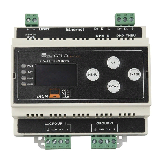
LED SPI-2 Install Control Panel A) OLED display MENU button C) UP button D) DOWN button ENTER button DMX LED (Blue) G) LINK LED (green) ACT LED (Orange) POWER LED (Red) Fig. 11 ● Use the MENU button to exit the current submenu and to return to the Main Menu. -
Page 21: Menu Overview
LED SPI-2 Install Menu Overview Product code: 50412... -
Page 22: Main Menu Options
LED SPI-2 Install Main Menu Options Upon start-up the display will show software version and the current settings. The main menu has the following options: Press the UP/DOWN buttons to navigate through the main menu. 02) Press the ENTER button to open the submenus. -
Page 23: Operating Mode
LED SPI-2 Install Operating Mode In this menu you can choose the desired Operating mode. Press the UP/DOWN buttons to navigate through the main menu. 02) Press the ENTER button to confirm your setting. Personality In this menu you can choose the desired DMX mode. -
Page 24: Output 1 / Output 2
LED SPI-2 Install Output 1 / Output 2 In this menu you can choose the settings for the desired Output Port. If you have chosen Output 1, the display will show: Press the UP/DOWN buttons to select one of the 3 submenus: ●... -
Page 25: User Color
LED SPI-2 Install User Color In this menu you can set the desired color. If you have chosen User Color, the display will show: Press the UP/DOWN buttons to select one of the 3 manually adjustable colors: ● ● Green ●... -
Page 26: Automatic Programs
LED SPI-2 Install Automatic Programs In this menu you can set the desired auto program. If you have chosen Automatic, the display will show: Press the UP/DOWN buttons to select one of the 2 submenus: ● Program ● Speed Press the ENTER button to enter the desired menu. -
Page 27: Ip Mode
Press the ENTER button to confirm your desired protocol. DHCP IP In this menu you can set the DHCP IP. This means the LED SPI-2 will automatically search for the right IP configuration, when your controller has also been set to DHCP. Static IP In this menu you can set the Static IP. -
Page 28: Netmask
LED SPI-2 Install Netmask In this menu you can choose the desired Netmask. While in the main menu, press the UP/DOWN buttons to choose Set Netmask. Press the ENTER button to enter the menu. The display will show: Press the UP/DOWN buttons to select one of the 3 Netmasks: ●... -
Page 29: Display Invert
LED SPI-2 Install Display Invert In this menu you can choose to invert the LCD Display. While in the main menu, press the UP/DOWN buttons to choose Set Display. Press the ENTER button to enter the menu. The display will show: Press the UP/DOWN buttons to select one of the 2 options: ●... -
Page 30: Firmware Version
LED SPI-2 Install Firmware version In this menu you can view the current firmware version of your device. While in the main menu, press the UP/DOWN buttons to choose Firm Version. Press the ENTER button to enter the menu. The display will show:... -
Page 31: Dmx Channels
LED SPI-2 Install DMX Channels 17 Channels 17 CH Function Value Setting Master Dimmer 000–255 From low to high intensity (0–100 %) Foreground Color Red 000–255 From low to high intensity (0–100 %) Foreground Color Green 000–255 From low to high intensity (0–100 %) Foreground Color Blue 000–255... -
Page 32: 34 Channels
LED SPI-2 Install 34 Channels Output Port 1 CH 1 - CH17 Output Port 2: CH18 - CH34 34 CH Function Value Setting Master Dimmer Port 1 000–255 From low to high intensity (0–100 %) Foreground Color Red 000–255 From low to high intensity (0–100 %) Foreground Color Green 000–255... - Page 33 LED SPI-2 Install Output Port 2 Master Dimmer Port 2 000–255 From low to high intensity (0–100 %) Foreground Color Red 000–255 From low to high intensity (0–100 %) Foreground Color Green 000–255 From low to high intensity (0–100 %) Foreground Color Blue 000–255...
-
Page 34: 510 Channels
Pixel 170 Green 000–255 From low to high intensity (0–100 %) Pixel 170 Blue 000–255 From low to high intensity (0–100 %) UID number The unique identification number of the device (UID) for the LED SPI-2 is 29B4. Product code: 50412... -
Page 35: Troubleshooting
LED SPI-2 Install Troubleshooting This troubleshooting guide contains solutions to problems which can be carried out by an ordinary person. The device does not contain user-serviceable parts. Unauthorized modifications to the device will render the warranty void. Such modifications may result in injuries and material damage. -
Page 36: Maintenance
LED SPI-2 Install Maintenance Safety Instructions for Maintenance DANGER Electric shock caused by dangerous voltage inside Disconnect power supply before servicing or cleaning. WARNING Risk of burns due to hot surface Allow the device to cool down for at least 15 minutes before servicing or cleaning. -
Page 37: Basic Cleaning Instructions
LED SPI-2 Install Basic Cleaning Instructions The external lens of the device must be cleaned periodically in order to optimize the light output. The cleaning schedule depends on the conditions at the site where the device is installed. When smoke or fog machines are used at the site, the device will need more frequent cleaning. -
Page 38: Deinstallation, Transportation And Storage
LED SPI-2 Install Deinstallation, Transportation and Storage Instructions for Deinstallation WARNING Incorrect deinstallation can cause serious injuries and damage of property. ● Let the device cool down before dismounting. ● Disconnect power supply before deinstallation. ● Always observe the national and site-specific regulations during deinstallation and derigging of the device. - Page 39 LED SPI-2 Install Product code: 50412...
- Page 40 ©2021 Showtec...
Need help?
Do you have a question about the LED SPI-2 and is the answer not in the manual?
Questions and answers