
Subscribe to Our Youtube Channel
Related Manuals for Doran 4300 Series


Summary of Contents for Doran 4300 Series
- Page 1 4300 Series Checkweigh Indicator Technical Manual MAN334 – Rev 5.3 Doran Scales, Inc. www.doranscales.com...
-
Page 2: Table Of Contents
Table of Contents Introduction ........................... 1 Unpacking Your Scale ........................1 4300 Indicator Specifications ......................2 Scale Annunciators .......................... 3 Power Up ............................4 Basic Weighing Operation ........................ 4 ZERO ..............................4 UNITS .............................. 4 PRINT ............................... 4 OVER ............................... 5 UNDER ............................. - Page 3 Parameter Groups ......................... 19 Legal for Trade Restrictions ......................19 Audit Counters ..........................19 Software Part Number and Revision Level ..................19 Capacity and Calibration - 1 CAL ....................20 General Settings - 2 Cnfg ....................... 23 Serial (RS232) Port 1 - 3 SEr1 ......................26 Serial (RS232) Port 2 - 4 SEr2 ......................
-
Page 4: Introduction
Introduction Thank you for purchasing a Doran Scales product. Please read this manual to ensure obtaining all the benefits that the indicator can provide. This manual is intended for revision 5.3 and greater scales. If required, Doran can upgrade the software in your scale to the current revision. -
Page 5: 4300 Indicator Specifications
4300 Indicator Specifications NTEP Certificate Class III – 10,000d; Cert. #97-038A1 CWM Certificate Class III – 10,000d; Cert. #AM-5201 Enclosure 304 Stainless Steel Product Dimensions 10” W x 6.75” H x 3.5” D Environmental Protection IP69K Legal for Trade 14 F to 104F (-10 C to +40 C) Temperature Range Resolution Range 200d to 50,000d... -
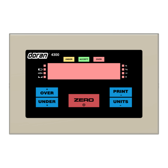
Page 6: Scale Annunciators
Fig. 1: Model 4300 Front Panel Layout The operational controls for the Model 4300 consist of the ZERO, PRINT, UNITS, OVER and UNDER buttons. A six digit LED display is used to display weight and operator messages during scale operation. Three lights, above the LED display indicate checkweighing status. -
Page 7: Power Up
Motion indicator. This symbol represents motion or instability of the weight. The annunciator will illuminate when motion is sensed on the platform. Changes in weight, vibration or air currents can cause the scale to go into motion. Under illuminates to indicate weight is below the Under target and above the Low target or flashes if below the Low target. -
Page 8: Over
There are many parameters that customize the control of manual and automatic transmission of data. Data can be transmitted via standard RS232, Ethernet, WiFi, Bluetooth or USB. Contact Doran Tech Support at tech@doranscales.com for support. OVER OVER allows entry of the upper checkweighing limits. It is also used to increment a checkweighing value that is being modified. -
Page 9: Battery Operation
Battery Operation The 4300 can be optionally configured with a self-contained Rechargeable Sealed Lead-Acid battery and charging circuit, both internal. The scale is designed to run continuously for up to 60 hours with a single 350 ohm load cell. To maximize battery life, leave the auto-off timer enabled which will automatically power down the scale after a period of non-use. -
Page 10: Three Band Checkweighing
Three Band Checkweighing Three band checkweighing classifies weighments into over, accept and under. The default configuration is three band checkweighing. Note that lb:oz is not supported for checkweighing limits. Three Band Checkweighing ( 9.1 C.o. set to operation starting with 3 ) 1. -
Page 11: Five Band Checkweighing
Five Band Checkweighing Five band checkweighing classifies weighments into high, over, accept, under and low. Note that lb:oz is not supported for checkweighing limits. Five Band Checkweighing ( 9.1 C.o. set to operation starting with S ) 1. Press ZERO 2. -
Page 12: Weight Reference Entry Of High And Low Limits ( 9.2 C.e. Set To Pb )
Weight Reference Entry of High and Low Limits ( 9.2 C.E. set to Pb ) 1. Press ZERO 2. Place an item of the desired weight on the scale platform 3. Press and hold the OVER or UNDER until the display reads High or louu respectively 4. -
Page 13: Installation Guide
Installation Guide Fig. 2: Motherboard Layout Removing and Replacing the Rear Panel Before you remove the rear panel, remove AC power. Power down the scale if the optional battery power is present. Removing the rear panel requires a 5/16” nut driver. To replace the rear panel and achieve a tight seal, each screw requires a rubber bonded washer and the gasket needs to be in place. -
Page 14: Load Cell Connection
Load Cell Connection Load cell connections are made through terminal block TB1. The power cord connects to terminal block TB5 adjacent to the transformer. Fig. 3: Load Cell and Power (lower left of board) 4 wire load cell 6 wire load cell J1 Jumper J2 Jumper Load Cell Input (TB1) -
Page 15: Power Connection And Fuse
Power Connection and Fuse Power input is located at terminal block TB5, next to the fuse and black transformer. Neutral Ground Line (Hot) Make sure power is off before replacing the fuse. The scale's fuse (F1) is located next to the power terminal (J1). The scale has a filtered power supply to reduce the effects of normal line noise, but it cannot limit severe fluctuations. - Page 16 TB3 RS232 and Remote Switch Connections Description RS232 Port 1 Receive (RXD) RS232 Port 1 Transmit (TXD) Common Ground Remote Switch 1 Input Remote Switch 2 Input RS232 Port 2 Receive (RXD) RS232 Port 2 Transmit (TXD) Remote Switch Common 4.7Vdc RS232 Output RS232 Output...
-
Page 17: Output Connections
Output Connections Each output point consists of a current-sinking Darlington pair with a transient – suppression diode connected to +V. Jumpers JU7 and JU3 control whether +V is board-supplied 4.7 VDC or 12 VDC. One or the other jumper needs to be installed for output operation, but never both. -
Page 18: Calibration Guide
Calibration Guide Entering Calibration and Parameter Setup Mode Front Panel Access 1. Press and hold ZERO and UNITS simultaneously until the audit counters are displayed. 2. Ent Cd is displayed 3. Press ZERO 5 times, so that 5 is displayed, 4. -
Page 19: Set Scale Count By
Set Scale Count By After the capacity has been entered, count by (resolution) will automatically be set for a legal for trade 5000 division level. 1. After calibration, press UNITS. 2. The display will alternate between Cnt by and the current count by 3. -
Page 20: Scale Calibration Troubleshooting
Scale Calibration Troubleshooting The allowable load cell signal input range is 0.30 mV/V to 5.0 mV/V. 1. Calculate scale divisions by dividing the scale capacity by the count by. Example: For a 50 x 0.01 lb scale, divide 50 by 0.01 for a result of 5000d 2. -
Page 21: Scale Parameter Setup
Scale Parameter Setup Entering Calibration and Parameter Setup Mode Front Panel Access 1. Press and hold ZERO and UNITS simultaneously until the audit counters are displayed. 2. Ent Cd is displayed 3. Press ZERO 5 times, so that 5 is displayed, 4. -
Page 22: Parameter Groups
Parameter Groups The scale parameters are divided up into eight parameter groups. Each group contains related parameters. Below is a brief list describing each parameter group. Capacity and Calibration 1 CAL 2 CnFg General Settings Serial port #1 3 SEr1 Serial port #2 4 SEr2 5 Eth... -
Page 23: Capacity And Calibration - 1 Cal
Capacity and Calibration - 1 CAL Capacity Adjustment CAP Aj 1 lb / kg to 999,000 lb / kg 1 - 999000 Refer to calibration guide for more detail Count By Setup Menu CntBy Also known as resolution or division Selection limited by scale capacity 0.00002 Capacity/resolution (scale divisions) maximum value... - Page 24 Automatic Zero Tracking Range A2t * Weight within the specified number of divisions are automatically zeroed Zero tracking is off, no automatic zeroing Zero tracking to within 0.5 division Zero tracking to within 1 division Zero tracking to within 3 divisions Zero tracking to within 5 divisions Zero tracking to within 10 divisions Zero tracking to within 20 divisions...
- Page 25 Zero on Demand Enables or disable zero latching If ZERO is pressed, it is saved until the scale becomes stable. If the scale is in motion, the zero request is discarded. Print on Demand Enables or disables print latching If PRINT is pressed, the print request is saved until the scale becomes stable.
-
Page 26: General Settings - 2 Cnfg
General Settings - 2 Cnfg Unit Enable and Disable Determines which unit selections will be active Do not enter Convert selection menu Enter Convert selection menu pounds menu lb is active lb is non active kilograms menu kg is active kg is non active ounces menu oz is active... - Page 27 Push Button Enable and Disable P.b. Determines which buttons are active or inactive Do not enter push button selection menu Enter push button selection menu PRINT button pb is active pb is non active UNITS button pb is active pb is non active ZERO button pb is active pb is non active...
- Page 28 Threshold Level Entry Controls automatic printing features starting with A.P. +0.1% to +9.9% of capacity 0.1 - 9.9 Default setting is 1% Default dEFt Used to set parameters to factory default values Do not default Set parameters to default values Raw counts from the AD converter Counts Used for troubleshooting during calibration...
-
Page 29: Serial (Rs232) Port 1 - 3 Ser1
Serial (RS232) Port 1 - 3 SEr1 Data Output Mode Port 1 d.o.1 Transmit on demand. Transmit when the PRINT t.o.d. button is pressed. Auto Print 1. Transmit once only when scale A.P.1 becomes stable. Auto Print 2. Transmit once only when scale becomes stable. -
Page 30: Serial (Rs232) Port 2 - 4 Ser2
Baud Rate Port 1 br.1 1200 baud 2400 baud 4800 baud 9600 baud 14,400 baud 14.4 19,200 baud 19.2 28,800 baud 28.8 38,400 baud 38.4 Serial (RS232) Port 2 - 4 SEr2 Data Output Mode Port 2 d.o. 2 Transmit on demand. Transmit when the PRINT t.o.d. - Page 31 Data Output Format Port 2 For. 2 Basic output format Basic Dual Print Format. Includes Kilogram weight. Basic Output for label printer Model 8000 emulation User definable print string with default values User definable print string with default values User definable print string with default values User definable print string WinSPC compatibility format Baud Rate Port 2...
-
Page 32: Wired Ethernet - 5 Eth
Wired Ethernet - 5 Eth Data Output Mode Ethernet d.o. E Transmit on demand. Transmit when the PRINT t.o.d. button is pressed. Auto Print 1. Transmit once only when scale A.P.1 becomes stable. Auto Print 2. Transmit once only when scale becomes stable. - Page 33 Static IP Address Assignment iP Adr Current IP address of the scale. Cannot be changed if the previous parameter is set to DHCP Subnet Mask Subnet Current subnet setting. Cannot be changed if set for DHCP IP Gateway 6ate Current IP Gateway. Cannot be changed if set for DHCP TCP Port Number Port...
-
Page 34: Wireless Ethernet - 6 Uufi
UDP IP Address UDPiP Current IP address that the scale will use to send UDP packets. UDP Port Number U Port Indicates the transmission UDP port number of the xxxxx scale. Wireless Ethernet - 6 uufi Data Output Mode wifi d.o. - Page 35 Data Output Format wifi For. UU Basic output format Basic Dual Print Format. Includes Kilogram weight. Basic Output for label printer Model 8000 emulation User definable print string with default values User definable print string with default values User definable print string with default values User definable print string WinSPC compatibility format iP.
- Page 36 Idle Timeout iDLE Number of seconds during which no data is transmitted or received before the connection is automatically closed. Default is 0 seconds. 0 - 65536 Setting the timer to 0 prevents disconnecting. Ethernet MAC Address nnac The unique Ethernet MAC address. Cannot be xxxxxx.xxxxxx changed.
-
Page 37: Bluetooth - 7 Bt
Bluetooth – 7 bt Data Output Mode Bluetooth d.o. bt Transmit on demand. Transmit when the PRINT t.o.d. button is pressed. Auto Print 1. Transmit once only when scale A.P.1 becomes stable. Auto Print 2. Transmit once only when scale becomes stable. -
Page 38: Usb - 8 Usb
USB – 8 USb Data Output Mode USB d.o. Usb Transmit on demand. Transmit when the PRINT t.o.d. button is pressed. Auto Print 1. Transmit once only when scale A.P.1 becomes stable. Auto Print 2. Transmit once only when scale becomes stable. -
Page 39: Checkweigh And Output Operation - 9 Oper
Checkweigh and Output Operation – 9 OPEr Checkweigh Operation C.o. Three band checkweighing Checkweigh status continuously active. Three band checkweighing Only active while weight is stable and inactive while the scale is in motion. Three band checkweighing Only active while the weight is above the threshold value (tHs parameter) and inactive when below. -
Page 40: Exit - 99 Don
Checkweigh Limit Entry C.E. Scroll from recalled value: Use the OVER or UNDER button to recall a limit. Then use the OVER and UNDER buttons to increase or decrease the recalled target value. Scroll from reference weight: Place an item on the platform and press the OVER or UNDER button to enter that weight as a target value. -
Page 41: Data Communications
Data Communications To confirm data has been transmitted, the display will show a "r" in the leftmost digit. Transmit on Demand ( tod ) In this mode, scale data is transmitted whenever PRINT is pressed, a remote switch configured for a PRINT command is pressed, or a print request is received at the serial port. -
Page 42: Data String Formatting
Data String Formatting Many predefined data formats are available with the 4300. This allows for flexibility when communicating with a database, printer, remote display or other devices. The LB1-4 custom data strings provide the opportunity to define a custom print string up to 64 characters in length. - Page 43 Print String Description Label Printer Output Format <p> Weight Polarity Negative weight “-”, positive weight <FR”L1”><LF><?><LF><p><xxxx.xx><LF space (20h) ><uu><LF><"GS"><LF><MOT><LF><p> <xxxx.xx> Weight Data fixed field <xxxx.xx><LF><kg><LF><P1,1><LF> of 6 digits plus decimal. In overload or underload “-------”. Leading zeros Sample Print String are spaces (20h) FR"L1"...
- Page 44 Print String Description Custom Data String 1 (\x\w \u \m\r\l) <STX> Start of Text (02h) <p> Weight Polarity <STX><p><xxxx.xx><SP><uu><SP> Negative weight “-”, positive weight <MOT><CR><LF> space (20h) <xxxx.xx> Weight Data fixed field Sample Print String of 6 digits plus decimal. In overload ±--10.05-lb or underload “-------”.
- Page 45 Print String Description Custom Data String 3 (\xID:\i \w \u \m\r\l) <p> Weight Polarity Negative weight “-”, positive weight <STX><”ID:”> space (20h) <SP><p><xxxx.xx><SP><uu><SP><MO <xxxx.xx> Weight Data fixed field T><CR><LF> of 6 digits plus decimal. In overload or underload “-------”. Leading zeros Sample Print String are spaces (20h) ID:00-±--10.05-lb...
-
Page 46: Custom Data String Configuration
Custom Data String Configuration Command Length Description Battery Status. Low: “batt” OK: “BATT” Motion aperture (“0.5”, “1”, “2”, “3”, “5”, “10”) Threshold: 2 digits, decimal, and “%” \hxx HEX byte. “xx” can be 00 through FF Linefeed. ASCII 0x0A 0 or 3 Motion status. - Page 47 Plain text can be inserted into the data string. No control character or slash is necessary for plain text entry. To download a custom data string, the string must be prefaced by a command to tell the indicator to expect a custom print string. ELx<string>¿...
-
Page 48: Indicator Commands
Indicator Commands All serial commands require a carriage return (0x0D) as a terminator. Commands can be entered on any communication option or serial port. W, w Weight is transmitted out all enabled ports in the format selected for each port. Wx, wx Custom data string Lb1-4 can be requested to transmit out all ports. - Page 49 Wireless ethernet is echoed to USB Clears all ‘x’ commands xhbn Enables ethernet “heartbeat” text. Every 30 seconds of ethernet inactivity, hex value 0xCE is output. xhbf Disables ethernet “heartbeat” text. For a complete protocol, please request this document from Doran Technical Support at tech@doranscales.com.
-
Page 50: 4-20Ma Analog Output Option
4-20mA Analog Output Option Introduction The 4-20mA Analog Output Option is used to provide an analog output that is proportional to the weight on the scale platform. The option board provides an active power loop for the communications. Because of the inherent noise immunity present in a current loop, an isolated 4-20mA analog output is ideal for use in noisy environments. -
Page 51: Wired Ethernet Option
Wired Ethernet Option The Wired Ethernet Option (EXOPT302) connects your Excel Series scale to an Ethernet network. The Ethernet module is installed inside the indicator enclosure. The NEMA4X sealed RJ-45 Ethernet connector is bulkhead mounted to the rear panel of the indicator. -
Page 52: Wireless 802.11B/G Ethernet Option
Wireless 802.11b/g Ethernet Option The Wireless Ethernet Option (EXOPT303) connects your 4300 scale to a wireless network. The Wireless Ethernet Option is fully compliant with the 802.11b/g wireless network standard. Wireless communications are protected by up to a 128-bit security encryption. -
Page 53: Troubleshooting Wifi
If the scale is having trouble connecting, consider repositioning the scale and its antenna to strengthen the connection. Once the scale is connected to Doran’s terminal program Dimension, the exact signal strength can be found using the SWB remote command. See the below table for a... -
Page 54: Bluetooth Option
Bluetooth Option Doran Scale’s Bluetooth option is a Class 3, Bluetooth 4.0, configured for SPP. The Bluetooth option does not require any external antenna for communication. Once paired, the Bluetooth module will function as a wireless RS232 serial cable. Each Bluetooth module has an individual 12-digit address i.e. -
Page 55: Bluetooth Pairing Instructions
Bluetooth Pairing Instructions The following example connects the scale to a Toshiba Bluetooth Stack running on a Windows PC. Click New Connection Click Next The driver will search for the scale. - Page 56 Select Dual-SPP and click Next Click Next once to pair Right-click Dual-SPP and choose Connect...
- Page 57 Click Yes to connect Right-click Dual-SPP and choose Detail… The COM number will be displayed...
- Page 58 Right-click Dual-SPP and choose Connect...
-
Page 59: Troubleshooting
Troubleshooting If any problem persists, contact Doran Tech Support at tech@doranscales.com Problem What to Do or Check Examine the weighing platform for any interferences. Be Weight reading will not sure that nothing is inside the platform, under the load cell... -
Page 60: Scale Messages
Scale Messages Message Meaning ZERO pressed and held past needed period Rel Pb Password enabled PASSon Invalid value entry or screen timeout Abort Calibration error: motion detected Er nno The scale is reading an overload condition Ovr Ld The scale is reading an underload condition Udr Ld “Loading Zero”... -
Page 61: Default To Factory Settings
Default to Factory Settings To return the setup parameters to factory default, follow these steps. 1. Enter Calibration Front Panel Access 1. Press and hold ZERO and UNITS simultaneously until the audit counters are displayed. 2. Ent Cd is displayed 3. - Page 62 Doran Scales, Inc. 883 Enterprise Ct. St. Charles, IL 60174 www.doranscales.com...
Need help?
Do you have a question about the 4300 Series and is the answer not in the manual?
Questions and answers