Advertisement
Quick Links
ISTR - 980 / 01
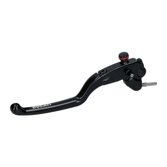
Kit leva freno in alluminio - 96180631AA (Nero) - 96180631AB (Argento)
Aluminium brake lever kit - 96180631AA (Black) - 96180631AB (Silver)
Simbologia
Per una lettura rapida e razionale sono stati impiegati simboli che
evidenziano situazioni di massima attenzione, consigli pratici o
semplici informazioni. Prestare molta attenzione al significato dei
simboli, in quanto la loro funzione è quella di non dovere ripete-
re concetti tecnici o avvertenze di sicurezza. Sono da considerare,
quindi, dei veri e propri "promemoria". Consultare questa pagina
ogni volta che sorgeranno dubbi sul loro significato.
Attenzione
La non osservanza delle istruzioni riportate può creare una situa-
zione di pericolo e causare gravi lesioni personali e anche la morte.
Importante
Indica la possibilità di arrecare danno al veicolo e/o ai suoi compo-
nenti se le istruzioni riportate non vengono eseguite.
Note
Fornisce utili informazioni sull'operazione in corso.
Riferimenti
I particolari evidenziati in grigio e riferimento numerico (Es.
rappresentano l'accessorio da installare e gli eventuali componenti
di montaggio forniti a kit.
I particolari con riferimento alfabetico (Es.
componenti originali presenti sul motoveicolo.
Tutte le indicazioni destro o sinistro si riferiscono al senso di marcia
del motociclo.
Avvertenze generali
Attenzione
Le operazioni riportate nelle pagine seguenti devono essere
eseguite esclusivamente da un'officina autorizzata Ducati.
Attenzione
Le operazioni riportate nelle pagine seguenti se non eseguite a re-
gola d'arte possono pregiudicare la sicurezza del pilota.
Note
Documentazione necessaria per eseguire il montaggio del Kit è il
Manuale Officina, relativo al modello di moto in vostro possesso.
Note
Nel caso fosse necessaria la sostituzione di un componente del kit
consultare la tavola ricambi allegata.
1
Symbols
The symbols used in this manual are aimed at making reading di-
rect and easy. The symbols are used either to draw the reader's
attention on potentially hazardous conditions, or to give practical
advice or to supply general information. Pay the utmost attention
to these symbols as they are used to remind of technical principles
or safety measures which will not be repeated extensively. They
must therefore be considered as "reminders". Check with this page
in case of doubt about their meaning.
Failure to comply with these instructions may put you at risk and
lead to severe injury or death.
It indicates the possibility of damaging the motorcycle and/or its
components if the instructions are not followed.
It supplies useful information about the operation in progress.
References
1
)
The parts highlighted in grey and with a reference number (e.g.
) represent the accessory to be installed and any assembly compo-
nents supplied with the kit.
A
) rappresentano i
The parts with alphabetic reference (e.g.
components present on the motorcycle.
All left and right indications are referred to the motorcycle direc-
tion of travel (forward riding position).
General notes
The operations described in the following pages must be exclu-
sively carried out by a Ducati authorised service centre.
Carefully perform the operations on the following pages since they
might negatively affect rider safety.
The Workshop Manual of your motorcycle model is the documen-
tation required to assemble the Kit.
Should it be necessary to change any kit parts, please refer to the
attached spare part table.
Operating, servicing and maintaining a passenger vehicle or off-
highway motor vehicle can expose you to chemicals including en-
gine exhaust, carbon monoxide, phthalates, and lead, which are
known to the State of California to cause cancer and birth defects
or other reproductive harm. To minimize exposure, avoid breath-
ing exhaust, do not idle the engine except as necessary, service
your vehicle in a well-ventilated area and wear gloves or wash your
hands frequently when servicing your vehicle. For more informa-
tion go to www.P65Warnings.ca.gov/passenger-vehicle.
Warning
Important
Notes
Warning
Warning
Notes
Notes
Warning
1
A
) represent the original
Advertisement

Related Manuals for rizoma Ducati 96180631AA


Summary of Contents for rizoma Ducati 96180631AA
- Page 1 ISTR - 980 / 01 Kit leva freno in alluminio - 96180631AA (Nero) - 96180631AB (Argento) Aluminium brake lever kit - 96180631AA (Black) - 96180631AB (Silver) Simbologia Symbols Per una lettura rapida e razionale sono stati impiegati simboli che The symbols used in this manual are aimed at making reading di- evidenziano situazioni di massima attenzione, consigli pratici o rect and easy.
- Page 2 ISTR 980 / 01 Importante Important I componenti del kit possono essere soggetti ad aggiornamenti; The parts of the kit can be updated; for information always up to consultare il DCS (Dealer Communication System) per avere infor- date, please refer to DCS (Dealer Communication System). mazioni sempre aggiornate.
- Page 3 ISTR 980 / 01 Smontaggio componenti originali Removing the original components Smontaggio gruppo leva freno anteriore Front brake lever unit disassembly Attenzione Warning Prima di procedere allo smontaggio della leva originale (C) occorre Before removing the original lever (C) it is necessary to move the riportare, tramite il pomello (C2), la leva in posizione tutta chiusa.
- Page 4 ISTR 980 / 01 Posizionare la leva freno anteriore (C) e relativo pompante (C1) sul- Position the front brake lever (C) and the relevant damper rod (C1) la dima (E). on the template (E). Note Notes Accertarsi che la leva freno anteriore (C) impegni correttamente la Make sure the front brake lever (C) engages correctly in the rel- relativa sede sulla dima (E).
- Page 5 ISTR 980 / 01 Montaggio componenti kit Assembling the kit components Importante Important Verificare, prima del montaggio, che tutti i componenti risultino Before assembling, check that all parts are clean and in good con- puliti e in perfetto stato. Adottare tutte le precauzioni necessarie ditions.
- Page 6 ISTR 980 / 01 Posizionare sulla dima (E) la leva freno anteriore (1), accertandosi Position on template (E) the front brake lever (1), making sure its che il registro (1A) della stessa risulti tutto chiuso, e che il pompan- adjuster (1A) is fully closed and that the damper rod (1B) is free to te (1B), risulti libero di arretrare completamente e non costretto dal move back completely and not fixed by the retaining dowel (1C).
- Page 7 ISTR 980 / 01 3 Nm ± 10% Note Notes Applicare grasso bianco sulla porzione di pompante (1B), che viene Apply white grease on the damper rod (1B) part that is inserted in inserita sulla cuffia parapolvere (D1) e sui piani di scorrimento, su- the dust cap (D1) and on the sliding surfaces (upper and lower) of periore ed inferiore della leva freno anteriore (1) sul corpo pompa the front brake lever (1) on the brake master cylinder (D).
- Page 8 ISTR 980 / 01 Note / Notes...
- Page 9 ISTR - 980 / 01 Kit levier de frein en aluminium - 96180631AA (Noir) - 96180631AB (Argenté) Kit Bremshebel aus Aluminium - 96180631AA (Schwarz) - 96180631AB (Silber) Symboles Symbole Pour une lecture rapide et rationnelle on a utilisé des symboles de Für ein schnelles und zweckmäßiges Lesen dieser Anleitung wur- mise en évidence de situations demandant une attention maxi- den Symbole verwendet, die Situationen, die höchste Aufmerk-...
- Page 10 ISTR 980 / 01 Important Wichtig Les composants du kit peuvent être soumis à des mises à jour ; Die Bestandteile des Kits können Aktualisierungen unterliegen. veuillez consulter le DCS (Dealer Communication System) pour des Lesen Sie stets die Angaben im DCS (Dealer Communication Sys- tem), um Informationen zur Verfügung stehen zu haben, die im- informations toujours actualisées.
- Page 11 ISTR 980 / 01 Dépose des composants d'origine Abnahme der Original-Bestandteile Dépose de l'ensemble levier de frein avant Abnahme der Einheit des Vorderradbremshebels Attention Achtung Avant de procéder à la dépose du levier d'origine (C), il faut le ra- Vor der Abnahme des Original-Hebels (C) muss dieser mit dem mener en position complètement fermée à...
- Page 12 ISTR 980 / 01 Positionner le levier de frein avant (C) et la tige amortisseur corres- Den Vorderradbremshebel (C) und das entsprechende Pumpele- pondante (C1) sur la jauge (E). ment (C1) auf der Schablone (E) anordnen. Remarques Hinweis S'assurer que le levier de frein avant (C) s’engage correctement Sicherstellen, dass der Vorderradbremshebel (C) korrekt auf der dans son logement sur la jauge (E).
- Page 13 ISTR 980 / 01 Pose des composants kit Montage der Kit-Bestandteile Important Wichtig Avant la pose, vérifier que tous les composants sont propres et en Vor der Montage überprüfen, dass alle Bestandteile sauber sind bon état. Prendre toutes les précautions nécessaires pour éviter und sich im perfekten Zustand befinden.
- Page 14 ISTR 980 / 01 Positionner le levier de frein avant (1) sur la jauge (E), en veillant Auf der Schablone (E) nun den Vorderradbremshebel (1) anordnen à ce que son élément de réglage (1A) soit complètement fermé et und sicherstellen, dass dessen Einstellscheibe(1A) vollkommen zu- que la tige amortisseur (1B) soit libre de reculer complètement et gedreht ist und das Pumpelement (1B) sich frei und ohne Behin- non forcée par la vis sans tête de fixation (1C).
- Page 15 ISTR 980 / 01 3 Nm ± 10% Remarques Hinweis Appliquer de la graisse blanche sur la partie de tige amortisseur Auf den Teil des Pumpelements (1B), der auf die Staubschutzkappe (D1) (1B) qui est insérée sur le soufflet cache-poussière (D1) et sur les gefügt wird und auf die oberen und unteren Gleitflächen des Vorder- plans de glissement supérieur et inférieur du levier de frein avant radbremshebels (1) am Bremszylinderkörper (D) weißes Fett auftragen.
- Page 16 ISTR 980 / 01 Remarques Hinweis...
-
Page 17: Advertências Gerais
ISTR - 980 / 01 Conjunto manete de travão de alumínio - 96180631AA (Preta) - 96180631AB (Prateada) Aluminium brake lever kit - 96180631AA (Black) - 96180631AB (Silver) Símbolos Symbols Para uma leitura rápida e racional foram empregues símbolos que The symbols used in this manual are aimed at making reading di- evidenciam situações de máxima atenção, conselhos práticos ou rect and easy. - Page 18 ISTR 980 / 01 Importante Important Os componentes do conjunto podem sofrer atualizações; consulte The parts of the kit can be updated; for information always up to o DCS (Dealer Communication System) a fim de obter informações date, please refer to DCS (Dealer Communication System). sempre atualizadas.
- Page 19 ISTR 980 / 01 Desmontagem dos componentes originais Removing the original components Desmontagem do grupo manete de travão dianteira Front brake lever unit disassembly Atenção Warning Antes de proceder com a desmontagem do manete original (C) é Before removing the original lever (C) it is necessary to move the necessário recolocar, por meio do botão (C2), o manete em posição lever in the fully closed position by means of knob (C2) The same totalmente fechada.
- Page 20 ISTR 980 / 01 Posicione o manete de travão dianteira (C) e o relativo bombeador Position the front brake lever (C) and the relevant damper rod (C1) (C1) na forma (E). on the template (E). Notas Notes Certifique-se de que o manete de travão dianteira (C) usa correta- Make sure the front brake lever (C) engages correctly in the rel- mente a relativa sede na forma (E).
- Page 21 ISTR 980 / 01 Montagem dos componentes do conjunto Assembling the kit components Importante Important Verifique, antes da montagem, se todos os componentes estão Before assembling, check that all parts are clean and in good con- limpos e em perfeito estado. Adote todas as precauções necessá- ditions.
- Page 22 ISTR 980 / 01 Posicione na forma (E) o manete de travão dianteira (1) certifican- Position on template (E) the front brake lever (1), making sure its do-se de que o aperto (1A) do mesmo esteja totalmente fechado adjuster (1A) is fully closed and that the damper rod (1B) is free to e que o bombeador (1B) fique livre de retrair-se completamente e move back completely and not fixed by the retaining dowel (1C).
- Page 23 ISTR 980 / 01 3 Nm ± 10% Notas Notes Aplique graxa branca na porção de bombeador (1B), que é inserida Apply white grease on the damper rod (1B) part that is inserted in na tampa de proteção anti-pó (D1) e nos planos de deslizamento, the dust cap (D1) and on the sliding surfaces (upper and lower) of superior e inferior do manete de travão dianteira (1) no corpo da the front brake lever (1) on the brake master cylinder (D).
- Page 24 ISTR 980 / 01 Notas / Notes...
-
Page 25: Advertencias Generales
ISTR - 980 / 01 Kit maneta freno de aluminio - 96180631AA (Negro) - 96180631AB (Plata) アルミニウム製ブレーキレバーキット - 96180631AA (ブラック) - 96180631AB (シルバー) Símbolos シンボル Para que la lectura resulte más rápida y racional, se han utilizado 素早くかつ合理的に読み進めることができるように、本マニュア símbolos que evidencian situaciones de máxima atención, conse- ルではいくつかのシンボルを導入し、最大限の注意を払う必要が... - Page 26 ISTR 980 / 01 Importante 重要 Es posible que los componentes del kit sean actualizados; consul- キットの構成部品は更新されることがあります。DCS (Dealer tar el DCS (Dealer Communication System) para tener información Communication System) から常に最新の情報をチェックするよ siempre al día. うにしてください。 Atención 警告 Par el montaje del kit, es obligatorio utilizar el accesorio con el cód. キットの取り付けには、アクセサリー...
- Page 27 ISTR 980 / 01 Desmontaje componentes originales オリジナル構成部品の取り外し Desmontaje grupo maneta freno delantero フロントブレーキレバーユニットの取り外し Atención 警告 Antes de desmontar la maneta original (C) es preciso colocarla en オリジナルのレバー (C) を取り外す前に、アジャスター (C2) で posición completamente cerrada por medio del mecanismo (C2). レバーをすべて閉じた位置にあわせてください。枠図...
- Page 28 ISTR 980 / 01 Posicionar la maneta freno delantero (C) y su grupo de bombeo (C1) フロントブレーキレバー (C) とポンピングロッド (C1) を治具 en el patrón (E). (E) に取り付けます。 Notas 参考 Asegurarse de que la maneta freno delantero (C) se encaje correc- フロントブレーキレバー...
- Page 29 ISTR 980 / 01 Montaje componentes kit キット部品の取り付け Importante 重要 Antes del montaje, comprobar que todos los componentes se en- 取り付けの前に全ての部品に汚れがなく、完璧な状態であること cuentren limpios y en perfecto estado. Adoptar todas las precau- を確認してください。作業する部分が破損しないように、必要な ciones necesarias para evitar dañar cualquier parte en la que se すべての予防措置を講じてください。...
- Page 30 ISTR 980 / 01 Posicionar la maneta freno delantero (1) en el patrón (E), asegurán- 治具 (E) にフロントブレーキレバー (1) を取り付けます。このと dose de que su dispositivo de ajuste (1A) esté todo cerrado y que き、アジャスター (1A) が完全に閉じていること、またポンピン el grupo de bombeo (1B) pueda retroceder completa y libremente, グロッド...
- Page 31 ISTR 980 / 01 3 Nm ± 10% Notas 参考 Aplicar grasa blanca en la porción de grupo de bombeo (1B) que se ポンピングロッド (1B) の一部分にホワイトグリースを塗布しま introduce en la protección guardapolvo (D1) y en los planos de des- す。ポンピングロッドをダストカバー (D1) とスライド面に挿入 lizamiento superior e inferior de la maneta freno delantero (1) en el し、フロントブレーキレバー...
- Page 32 ISTR 980 / 01 Notas / 参考...
- Page 33 レース専用部品 ご注文書 ご注文商品 商品名 P/N 商品名 P/N 商品名 P/N 商品名 P/N 商品名 P/N お客様ご記入欄 私は上記レース専用部品を下記車両に装着し、サーキット走行のみに 利用し、一般公道には利用しません。 車台番号 ZDM モデル名 お客様署名 ご注文日 ドゥカティ正規ネットワーク店記入欄 お客様に上記レース専用部品を販売し、レース専用部品のご利用方法を 説明いたしました。 販売店署名 販売日 年 月 日 販売店様へお願い 1. 上記ご記入の上、弊社アフターセールス 部までFAX してください 。FAX : 03 - 6692 - 1317 1. 上記ご記入の上、弊社アフターセールス 部までFAX してください 。FAX : 03 - 6692 - 1317 2.
Need help?
Do you have a question about the Ducati 96180631AA and is the answer not in the manual?
Questions and answers