Sony EBS-SP10 User Manual
Monitors: external tv tuner with hospitality support.
Hide thumbs
Also See for EBS-SP10:
- Dimensions (1 page) ,
- Brochure & specs (12 pages) ,
- Datasheet (1 page)

Related Manuals for Sony EBS-SP10


Summary of Contents for Sony EBS-SP10
-
Page 1: User Manual
SP-Tune for Sony User Manual Manual# 040726 Model: EBS-SP10 205 Commercial Court Morganville, NJ 07751 www.auroramultimedia.com... -
Page 2: Table Of Contents
INTRODUCTION ...2 ACCESSORIES ...2 SUPPORTED IR TRANSMITTER(S) AND BASIC KEY FUNCTIONS ...2 QUICK START GUIDE ...4 SONY PLASMA SETTINGS ...5 LED FUNCTIONS ...6 CONNECTIONS ...6 A/V & C ONTROL CONNECTORS ...8 CONNECTOR RJ11 S ERVICE ORT CONNECTOR ...8 OWER CONNECTOR OPERATING THE SP-TUNE...8... -
Page 3: Introduction
1 Introduction The SP-TUNE is a high quality TV Tuner/Scaler. The SP-TUNE supports advanced functionality, like video format /scan rate conversions, audio effects, Closed Captioning decoding and output, V-Chip functions, cloning capabilities (using the RS-232 port), Sleep Timer, etc. The SP-TUNE video/audio/control output is intended to be connected to various types of displays. The SP-TUNE uses the IR detector of the display device or can use the built in IR sensor. - Page 4 The SP-TUNE is controlled using an IR remote controller. It utilizes IR receiver of the display via the Control S output port or the built in IR sensor. The SP-TUNE unit is compatible with the Sony IR remote transmitter(s) below (see Fig.1 & 2). These transmitter(s) can be used to control the SP-TUNE.
-
Page 5: Quick Start Guide
1. Make sure the SP-TUNE unit and the Sony Display are both disconnected from power. 2. Connect the SP-TUNE unit to the Sony Plasma Display using the supplied cable harness. Each cable on the harness is labeled for the appropriate connection. Make certain to plug the Control S phono connector into the Control S output of the display. -
Page 6: Sony Plasma Settings
8. The subsequent behavior of SP-TUNE depends on its mode of operation (see the “Operating Modes” chapter). A quick way to test correctness of setup is to use the “Power” key of Sony remote to switch the “Power” state of SP-TUNE on – (1) when pressing key on remote the upper LED should blink fast (signaling the IR signal reception);... -
Page 7: Led Functions
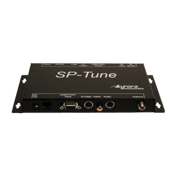
Lower LED: • Switches ON when a control packet is sent to Sony Display Panel through RS-232. Switched OFF when a valid reply to the control packet is received back. Therefore, if this LED is ON for a long time, probably there are problems with the Panel Connection (or Panel power supply). - Page 8 • “VGA”-connector Component (RGB+syncs, RGB with sync on green, or YPbPr) video input • Audio inputs/outputs (8pin mini DIN) • RS-232 port for display control • Logic input port for current sensors • IR Output for IR control of devices without RS-232 control •...
-
Page 9: Rf Connector
The coaxial connector (ANT) of SP-TUNE is RF signal input – either aerial or cable TV, UHF/VHF, if the SP-TUNE shall be used as TV tuner. 7.3 RJ11 Service Port connector RJ11 connector of SP-TUNE is used as a service port for Sony. Nothing should be connected to this port. Warning: Damage may occur if plug into a different port such as a phone line. -
Page 10: Remote Control Functions
8.1 Remote Control Functions In the Stand-alone and Service modes, the SP-TUNE is controlled using one of directly supported IR transmitters by Sony. When no menu is active, usual keys of IR transmitter can be utilized to change volume level and switch channels. -
Page 11: Menu Structure
Key: “ON/STBY” Switch SP-TUNE power on/off. The display panel is switched accordingly if it is connected using the RS- 232 port or IR output port. 8.2 Menu Structure The menu system allows a user to control various aspects of SP-TUNE configuration. For all menus, up/down arrows move the cursor (yellow “selection”... -
Page 12: Video Settings
This menu allows control of various “general” aspects of SP-TUNE behavior. Note that the *- marked options are accessible only in Service mode, and not in Stand-alone mode. A/V Input – Allows user to select the audio/video input source (among the built-in Tuner and available AV-inputs) Current time –... -
Page 13: Audio Settings
Timer Logo -- Time, in seconds, for which the “logo” picture is shown after SP-TUNE powering on. Video Position -- Opens the “Video position” submenu, allowing control of picture position on screen. 8.5 Audio Settings Volume -- Selects the current (default) volume level Spatial Effect -- Specifies the strength of 3D-spatial effect 8.6 Tuner Settings... -
Page 14: Panel Settings
AV inputs. 8.7 Panel Settings This menu controls various aspects of interaction with Sony Plasma Display through the RS-232 port. This menu is accessible in Service mode only (not in Stand-alone). All these parameters do not affect behavior of SP-TUNE, they are transferred to Display Panel in control packets over the serial port and should be interpreted by Display Panel. -
Page 15: Cc Settings
Orbit Enable -- Allows the enabling of Orbit mode on a per channel basis. Orbit Range -- Selects how much orbit movement will occur. Orbit Cycle -- Determines how often it will orbit. 8.8 CC Settings This menu control Closed Caption decoder – CC signal type, and CC text color. CC State -- CC decoder state: Off –... -
Page 16: Troubleshooting
If the password is reset, the user is prompted to enter new password on his/her first access to V-Chip limit. For all subsequent accesses the user will have to use the password that was specified during the first access. In the event the password is forgotten the V-Chip settings can reset by holding the enter button for 5 sec. -
Page 17: Firmware And Startup Picture Update
9 Firmware and Startup Picture update The internal software of SP-TUNE (the firmware) can be updated. This may be necessary to fix errors corrected in the newer releases of the firmware, or to enhance functionality. The similar procedure is used to update the “logo picture” that can be shown by SP-TUNE for a predefined time after power on. For the update procedure the serial port of the SP-TUNE must be connected to the RS-232 (“COM”) port of a PC-compatible personal computer, running MS-Windows 98, 2k, or XP operating system. -
Page 18: Specifications
Audio stereo IN/OUT – 8 pin mini DIN. Requires adapter cable with 4 pairs of RCA connectors. ANT (aerial) IN – RF UHF/VHF Sony Service Port – RJ11 Component YPbPr/RGB+HV OUTPUT – 15-pin female VGA-compatible connector. IR IN – 3.5mm TRS (Tip – Signal, Ring – 12v (if jumped internally), Sleeve – Ground) IR OUT –... -
Page 19: Dimensions
6 – Composite audio Left IN 7 -- YPbPr audio Right IN 8 -- Right Line OUT 10.4 Dimensions Height: 0.96” Depth: 4.18” Length: 7.30” Plus 1.39” (35.3 mm) with mounting brackets 10.5 Weight Approx. 0.8 lbs for SP-Tune unit and 2 lbs with all accessories and boxed... -
Page 20: Limited Warranty
11 Limited Warranty Aurora Multimedia Corp. Warrants that this product is free of defects in both materials and workmanship for a period of 24 months for parts and labor from date of purchase. During the warranty period, and upon proof of purchase, the product will be repaired or replaced (with same or similar model) at our option without charge for parts or labor for the specified warranty period (24 months parts and labor).
Need help?
Do you have a question about the EBS-SP10 and is the answer not in the manual?
Questions and answers