Advertisement
Quick Links
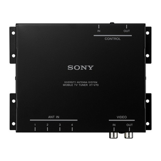
Mobile TV Tuner
Installation/Connections
Installation/Raccordements
Notice to dealers and installers
Please return this manual to the customer after the installation is completed.
Remarque à l'intention des distributeurs et des installateurs
Veuillez rendre ce manuel au client lorsque l'installation est terminée.
XT-V70
© 2005 Sony Corporation
Printed in Japan
1
1
2
3
4
×2
5.3 m
5 m
5
6
7
×2
8
9
0
qa
×6
×4
2
VIDEO OUT
AUX 3
TV tuner unit
Tuner de télévision
XT-V70
AV Center
CONTROL OUT
AV Center
XAV-A1
CONTROL IN
CONTROL OUT
Connection box XA-123
XM radio tuner (optional)
(supplied with XAV-A1)
XM tuner de radio (en option)
Boite de raccordement XA-123
(fournie avec XAV-A1)
Available only in the USA.
Disponible seulement aux Etats-Unis.
3
AV Center
AV Center
XAV-A1
Film antenna 5
Antenne film 5
RCA interconnects (5 m) 2
Interconnexions RCA (5 m) 2
Antenna input cable 6
AUX 3
* To the optional back camera or a video
Câble d'entrée d'antenne 6
equipment (to AUX 3).
* A une caméra arrière en option ou un
équipement vidéo (à AUX3).
VIDEO IN
TV antenna amplifier unit 4
Amplificateur d'antenne de télévision 4
VIDEO OUT
ANT IN
To a metal surface of the car
A la surface métallique de la voiture
Black
TV tuner unit
Noir
Tuner de télévision
Fuse (0.5 A)
XT-V70
Fusible (0,5 A)
To the +12 V power terminal which is
energized in the accessory position of the
ignition key switch.
Red
Be sure to connect the black ground lead to
CONTROL OUT
Rouge
it first.
A la borne d'alimentation +12 V traversee
par le courant a la position accessoire de la
Bus cable (5.3 m) 1
cle de contact.
Câble de bus (5,3 m) 1
Raccordez-y bien le fil de mise a la terre noir
en premier.
4
XT-V70
Hook-and-loop fastener 3
Hook-and-loop fastener 3
Patins adhésifs 3
Patins adhésifs 3
On installation surface
Sur la surface d'installation
2-597-470-12 (1)
5
Front pillar
Montant avant
Film antenna (left) 5
Film antenna (right) 5
Antenne film (droite) 5
Antenne film (gauche) 5
Antenna input cable 6
Câble d'entrée d'antenne 6
XAV-A1
6
1
2
Power supply point
2RR6P12A23200A
Point d'alimentation
Ceramic line
Ligne en
céramique
Align the upper edge of the
Temporary fastener
antenna with this line.
(cellophane tape, etc.)
Aligner l'extrémité supérieure de
Fixation temporaire
l'antenne sur cette ligne.
(ruban adhésif etc.)
7
×2
8
1
Spray bottle
Vaporisateur
Marking (cellophane tape, etc.)
Marque (ruban adhésif etc.)
2
Peel-off tab
Languette d'écaillage
3
Align the upper edge of the antenna with this line.
Aligner le bord supérieur de l'antenne sur cette ligne.
4
Squeegee 8
Raclette 8
WARNING
Front pillar
Montant avant
This equipment has been tested and found to comply with the
limits for a Class B digital device, pursuant to Part 15 of the FCC
Rules. These limits are designed to provide reasonable protection
against harmful interference in a residential installation. This
equipment generates, uses, and can radiate radio frequency
energy and, if not installed and used in accordance with the
instructions, may cause harmful interference to radio
communications. However, there is no guarantee that interference
Antenna input cable 6
will not occur in a particular installation. If this equipment does
Câble d'entrée d'antenne 6
cause harmful interference to radio or television reception, which
can be determined by turning the equipment off and on, the user
is encouraged to try to correct the interference by one or more of
the following measures:
— Reorient or relocate the receiving antenna.
— Increase the separation between the equipment and receiver.
— Connect the equipment into an outlet on a circuit different from
that to which the receiver is connected.
— Consult the dealer or an experienced radio/TV technician for
help.
TV antenna amplifier unit 4
Amplificateur d'antenne de
You are cautioned that any changes or modifications not expressly
télévision 4
approved in this manual could void your authority to operate this
equipment.
Owner's Record
The model and serial numbers are located on the bottom of the
unit.
Record the serial number in the space provided below.
Refer to these numbers whenever you call upon your Sony dealer
regarding this product.
Model No. XT-V70 Serial No.
Precautions
•This unit is designed for negative ground 12 V DC systems only.
•Do not get the wires under a screw, or caught in moving parts
(e.g. seat railing).
•Before making connections, turn the car ignition off to avoid
short circuits.
•Connect the red power input leads only after all other leads have
been connected.
•Run all ground wires to a common ground point.
Fuse replacement
When replacing the fuse, be sure to use one matching the
Marking (cellophane tape, etc.)
amperage rating stated on the original fuse. If the fuse blows,
Marque (ruban adhésif etc.)
check the power connection and replace the fuse. If the fuse blows
again after replacement, there may be an internal malfunction. In
such a case, consult your nearest Sony dealer.
Fuse (0.5 A)
TV antenna amplifier unit 4
Front pillar
Montant avant
Parts list (1)
•The numbers in the list are keyed to those in the instructions.
• Use 9 and 0 to organize cords.
Connection example (2)
Connection diagram (3)
Installing the TV tuner unit (4)
Notes
• Ensure that the mounting surface is clean.
• Do not install the TV tuner unit
– in locations subject to high temperatures.
– in locations subject to direct sunlight, warm air from heater
outlets, or other locations that can get hot.
• When attaching the hook-and-loop fastener to the bottom of the TV
tuner unit, do not cover the model name plate in the center.
Keep the units and connection cables apart.
The AV Center main unit, the monitor, TV tuner unit, and RCA
interconnects should not be in close proximity. Otherwise noise
interference may affect the TV picture.
Mounting the TV antenna
Mount the film antenna 5 to the car and connect the TV tuner
unit.
For directions on connecting the TV tuner unit, see also
"Connection diagram (3)".
Before mounting
•It may not be possible to mount the antenna on some cars.
- In cars with glass that does not transmit radio waves (infrared
reflecting glass, insulated glass, glass that is opaque to
electromagnetic waves, etc.), the signal reception will be
extremely poor.
- The antenna cannot be mounted in cars which have airbags in
the front pillars.
•Mount the antenna to the front window, in the specified location
and according to the specified dimensions.
- The supplied film antenna is designed for attaching only to the
front window. If attached to the rear window or elsewhere in
the car, the signal reception may be extremely poor.
Notes
• Once you have mounted the film antenna, do not attempt to remove
it and attach it again, as the adhesive will be considerably weakened.
Be sure to temporarily fasten the cable and antenna in place and
check that the cable has sufficient play before permanently attaching.
• During the mounting procedure, it will be necessary to remove the
front pillar molding to attach a ground wire.
When performing the installation yourself, if you decide it is too
difficult to remove the front pillar molding, please contact your
dealer for assistance. (Note that your dealer may charge a fee for
their assistance.)
Required items
Have the following items handy before beginning the mounting
procedure.
Marking (cellophane tape, etc.)
Marque (ruban adhésif etc.)
•Tools (Philips screwdriver, etc.)
•Cellophane tape
•Scissors
•Spray bottle (fill with 500 ml water and one or two drops of
detergent)
•Paper towels
Note
Mount the film antennas to the inside of the front window. Do not
mount the antennas anywhere other than the location described here.
Before attaching
Using the supplied cleaning cloth qa to wipe away any oil, wax, or dust
tat may be on the window.
Mounting position (5)
Précautions
Installation complete
•Cet appareil est conçu pour les systèmes 12 V CC avec masse
Film antenna mounting procedure
négative uniquement.
Check the film antenna 5 mounting position (6)
•Prenez garde de ne pas coincer les fils sous une vis ni dans des
parties mobiles (tels que les rails des sièges).
1 Align the film antenna power supply point with the lower
•Avant de procéder aux raccordements, coupez le moteur du
edge of the window's ceramic line and fasten temporarily in
véhicule afin d'éviter tout court-circuit.
place with cellophane tape (6-1).
•Raccordez le cordon d'alimentation rouge uniquement après
Do not remove the adhesive backing from the antenna yet.
tous les autres cordons.
The figure shows the results of this step, for the left antenna.
•Dirigez tous les fils de masse vers un point de masse commun.
Temporarily position the right antenna in the same manner.
2 Mark the left and right sides of the film antenna, using
Remplacement du fusible
cellophane tape, etc (6-2).
Lorsque vous remplacez le fusible, veillez à utiliser un fusible
dont l'ampérage correspond à celui indiqué sur le fusible
Remove the inner molding from the front pillars on
d'origine. Si le fusible fond, vérifiez le branchement de
both sides of the front window (7)
l'alimentation et remplacez le fusible. Si le fusible fond de
The figure shows an example of a car, such as a sedan or SUV,
nouveau après avoir été remplacé, cela peut révéler une
which as a handle mounted on the front pillar.
défaillance interne de l'appareil. Dans ce cas, consultez le
revendeur Sony le plus près de chez vous.
Notes
• The molding on the front pillar will be fastened in place with clips or
Fusible (0,5 A)
screws. When removing it, take care not to damage or deform it.
• When performing the installation yourself, if you decide it is too
difficult to remove the front pillar molding, please contact your
dealer for assistance. (Note that your dealer may charge a fee for
their assistance.)
Attach film antenna 5 (8)
Before attaching
Amplificateur d'antenne de télévision 4
• Remove the film antenna, which you previously fastened temporarily
in place, before beginning these steps.
• Cover the dashboard with a cloth to protect it from the water and
detergent.
Nomenclature (1)
• Clean the front window well to remove any dirt, oil, or anti-fogging
agent before beginning these steps.
•Les numéros de la liste correspondent à ceux du manuel.
1 Using a spray bottle, wet the inside of the front window well
•Utilisez 9 et 0 pour disposer les cordons.
with a mild detergent solution. The optimal solution is 500 ml
of water with one or two drops of detergent (8-1). (Pure
water will not work well for making fine adjustments.)
Exemple de raccordement (2)
2 Remove the clear backing from the film antenna. Using the
spray bottle, wet the exposed surface well with the mild
detergent solution (8-2).
•Grasp the peel-off tab and peel the clear backing off slowly.
Schéma de raccordement (3)
•Do not remove the protective sheet from the other side (the
side that faces the inside of the car) yet. You will remove that
sheet in step 8-4.
•Take care not to get dirt or fingerprints on the exposed
surface of the film antenna.
Installation du tuner TV (4)
When attaching the film antenna
Remarques
• Position the antenna vertically by aligning the upper edge of the
• Vérifiez que la surface de montage est propre.
antenna with the lower edge of the ceramic line. Position it
• N'installez pas le tuner de télévision
horizontally by aligning the edges with the marking (cellophane
- dans des endroits soumis à des températures élevées.
tape, etc.) that you previously placed on the window.
- dans des endroits soumis aux rayons directs du soleil, à de l'air
• Do not let the front window get dry as you are working. Spray it
chaud provenant des sorties du chauffage ou dans d'autres endroits
again with the detergent solution as needed.
susceptibles de devenir très chauds.
• Until the front window dries, you can slide the antenna to adjust
• Lorsque vous installez les patins adhésifs sous le tuner de télévision,
its position.
ne recouvrez pas la plaque portant le nom du modèle qui se trouve
• When you have the antenna positioned where you want it,
au centre.
remove the markings.
Séparez les appareils et les câbles de raccordement.
3 Stick the film antenna to the front window (8-3).
L'appareil principal du AV Center, le moniteur, le tuner de télévision et
le câble à broches RCA ne doivent pas être trop proches. Sinon, des
4 Use the supplied squeegee 8 to make sure the film antenna is
parasites risquent de perturber l'image du téléviseur.
well attached to the window (8-4).
•Hold the antenna so it does not move while using the
squeegee.
•Work from the center of the antenna outward.
Montage de l'antenne de télévision
•Work the squeegee along the length of the antenna, pushing
out air bubbles to obtain a good seal.
Montez l'antenne film 5 de la voiture et connectez le téléviseur.
•Do not rub the antenna too hard.
Pour les instructions sur le raccordement du téléviseur, également
voir le "Schéma de connexion (3)".
Note
Make sure that the film antenna is completely dry before
Avant le montage
continuing with the mounting procedure. Continuing before the
antenna is dry may cause it to come off the window.
•Le montage de l'antenne peut être impossible sur certaines
voitures.
5 Use paper towels to wipe away the excess detergent solution
- La réception du signal peut être très mauvaise pour les
and dry the antenna well.
voitures dont les vitres ne transmettent pas les ondes radio
We recommend you let the antenna dry for 3-4 hours.
(verre réfléchissant l'infrarouge, verre isolé, verre opaque aux
Do not try to rush the drying process by using a hair dryer or
ondes électromagnétiques etc.).
other heater. Doing so may damage the film antenna.
- L'antenne ne peut pas être montée sur des voitures à airbag
dans les montants avant.
Turn over. t
•Montez l'antenne au pare-brise, à l'emplacement spécifié et
conformément aux dimensions spécifiées.
- L'antenne film fournie est conçue uniquement pour la fixation
au pare-brise. Si elle est attachée à la vitre arrière ou ailleurs
dans la voiture, la réception du signal peut être très mauvaise.
Remarques
• Une fois l'antenne film montée, n'essayez pas de la retirer et de la
remonter, parce que l'adhésif sera considérablement affaibli. Mettez
provisoirement le câble et l'antenne en place et vérifiez que le câble a
un jeu suffisant avant de le fixer définitivement.
• Pendant le montage, la monture du montant avant devra être retirée
pour attacher le fil de mise à la terre.
Si vous faites l'installation vous-même, et décidez que le retrait de la
monture du montant avant est trop difficile, demandez l'assistance du
revendeur. (Notez que le revendeur peut vous demander de payer
son intervention.)
Articles requis
Prévoyez les articles suivants avant de commencer le montage.
•Outils (tournevis Philips etc.)
•Ruban adhésif
•Ciseaux
•Vaporisateur (rempli de 500 ml d'eau et d'une ou deux gouttes
de détergent)
•Serviettes en papier
Remarque
Montez les antennes film à l'intérieur du pare-brise. Ne les montez à
aucun endroit autre que ceux indiqués ici.
Avant la fixation
Éliminez toute huile, cire ou poussière sur le pare-brise avec le chiffon
de nettoyage qa fourni.
Position de montage (5)
Installation complète
Procédure de montage de l'antenne film
Vérifiez la position de montage de l'antenne film 5 (6)
1 Alignez le point d'alimentation de l'antenne film sur le bord
inférieur de la ligne en céramique de la vitre et mettez-la
provisoirement en place avec du ruban adhésif (6-1).
Ne retirez pas encore la protection arrière du ruban adhésif de
l'antenne.
L'illustration indique les résultats de cette étape pour l'antenne
gauche. Placez temporairement l'antenne droite de la même
manière.
2 Marquez les côtés droit et gauche de l'antenne film avec du
ruban adhésif etc. (6-2).
Retirer la monture interne des montants avant sur les
deux côtés du pare-brise (7)
L'illustration donne l'exemple d'une voiture, conduite intérieure
ou SUV, à volant monté sur le montant avant.
Remarques
• Les montures de montant avant sont fixées avec des pinces ou vis. Au
retrait, faites attention de ne pas les endommager ou déformer.
• Si vous effectuez l'installation vous-même, et que vous jugez le retrait
du montant avant trop difficile , demandez l'assistance de votre
revendeur. (Notez que l'intervention du revendeur peut être
payante.)
Fixation de l'antenne film 5 (8)
Avant la fixation
• Retirez l'antenne film, temporairement fixée précédemment, avant
de commencer cette procédure.
• Couvrez le tableau de bord avec un chiffon pour le protéger contre
l'eau et le détergent.
• Nettoyez bien le pare-brise pour éliminer la saleté, l'huile ou l'agent
antibrouillard avant de commencer cette procédure.
1 Mouillez bien l'intérieur du pare-brise avec un vaporisateur de
solution détergente douce. La solution optimale est 500 ml
d'eau avec une ou deux gouttes de détergent (8-1). (De l'eau
pure ne permettra pas de faire les ajustements précis.)
2 Retirez la protection transparente de l'antenne film. Mouillez
bien la surface exposée avec le vaporisateur de solution
détergente douce (8-2).
•Saisissez la languette d'écaillage pour lentement détacher la
protection transparente.
•Ne retirez pas encore la feuille de protection de l'autre côté
(le côté face à l'intérieur de la voiture). Elle sera retirée à
l'étape 8-4.
•Prenez garde de ne pas laisser de saleté ou de traces de
doigts sur la surface exposée de l'antenne film.
Fixation de l'antenne film
• Placez l'antenne verticalement en alignant le bord supérieur de
l'antenne sur le bord inférieur de la ligne céramique. Placez-la
horizontalement en alignant les bords avec les marques (ruban
adhésif etc.) antérieurement faites sur la vitre.
• Ne laissez pas le pare-brise sécher pendant que vous travaillez.
Vaporisez à nouveau de la solution détergente douce si nécessaire.
• Vous pouvez faire glisser l'antenne pour ajuster sa position tant
que le pare-brise est mouillé.
• Retirez les marques quand l'antenne est placée là où vous le
souhaitez.
3 Collez l'antenne film sur le pare-brise (8-3).
4 Assurez-vous que l'antenne film est bien attachée à la vitre
avec la raclette en caoutchouc 8 fournie (8-4).
•Tenez l'antenne de sorte qu'elle ne bouge pas en utilisant la
raclette.
•Allez du centre de l'antenne vers l'extérieur.
•Passez la raclette le long de l'antenne, en éliminant les bulles
d'air pour obtenir une bonne adhérence.
•Ne frottez pas l'antenne trop fort.
Remarque
Vérifiez que l'antenne film est entièrement sèche avant de
poursuivre la procédure de montage. Sinon elle pourrait se détacher
de la vitre.
5 Éliminez la solution détergente en excès et séchez bien
l'antenne avec les serviettes en papier.
Nous recommandons de laisser l'antenne sécher 3 à 4 heures.
Ne précipitez pas le séchage en utilisant un sèche-cheveux ou
autre chauffage. Cela pourrait endommager l'antenne film.
Voir au verso. t
Advertisement

Related Manuals for Sony XT-V70


Summary of Contents for Sony XT-V70
- Page 1 The model and serial numbers are located on the bottom of the unit. Record the serial number in the space provided below. Refer to these numbers whenever you call upon your Sony dealer regarding this product. Model No. XT-V70 Serial No.
- Page 2 Protective sheet Feuille de protection Power supply point Power supply point Point d’alimentation Point d’alimentation Peel off the Peel off the protective protective sheet. sheet. Détachez la Détachez la feuille de feuille de protection. protection. Temporary fastening Temporary fastening (cellophane tape, etc.) (cellophane tape, etc.) Fixation temporaire Fixation temporaire...
Need help?
Do you have a question about the XT-V70 and is the answer not in the manual?
Questions and answers