Table of Contents
Advertisement
Quick Links
xCORE-200 explorerKIT Hardware Manual
IN THI S DOC UMENT
Features
xCORE Multicore Microcontroller Device
GPIO headers (J1 & J3)
Gyroscope and accelerometer
USB connections
RGMII connection
xSYS connector
General purpose push-button switches
Servo connectors
User LEDs
QSPI Flash
24MHz Crystal Oscillator
Power connector
Operating requirements
Dimensions
xCORE-200 explorerKIT Portmap
xCORE-200 explorerKIT schematics
RoHS and REACH
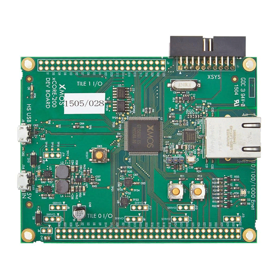
xCORE-200 explorerKIT is an evaluation board for the configurable xCORE-200
multicore microcontroller products from XMOS. It's easy to use and provides lots
of advanced features on a small, extremely low cost platform.
xCORE lets you software-configure the interfaces that you need for your system;
so with xCORE-200 explorerKIT you can configure the board to match your exact
requirements. The xCORE-200 multicore microcontroller has sixteen 32bit logical
cores that deliver up to 2000MIPs completely deterministically, making xCORE-200
explorerKIT an ideal platform for functions ranging from robotics and motion
control to networking and digital audio.
Publication Date: 2015/7/27
XMOS © 2015, All Rights Reserved
Document Number: XM007647C
Advertisement
Table of Contents

Subscribe to Our Youtube Channel
Related Manuals for XMOS xCORE-200 explorerKIT


Summary of Contents for XMOS xCORE-200 explorerKIT
- Page 1 The xCORE-200 multicore microcontroller has sixteen 32bit logical...
- Page 2 Hardware Manual 2/18 1 Features A block diagram of the xCORE-200 explorerKIT is shown below: Figure 1: xCORE-200 explorerKIT block diagram It includes the following features: A: xCORE-200 (XEF216-512-TQ128) Multicore Microcontroller device B: 32 GPIO connections from tile 0, arranged on a 0.1” grid C: 21 GPIO connections from tile 1, arranged on a 0.1”...
- Page 3 S: 24MHz Oscillator 2 xCORE Multicore Microcontroller Device xCORE-200 explorerKIT is based on a two-tile xCORE-200 device (XEF216-512- TQ128). Each tile is user-programmable, providing eight logical cores with a total of up to 1000 MIPS compute. A total of 53 general-purpose digital I/O have been brought out to header pins, providing tremendous flexibility for connecting...
- Page 4 Hardware Manual 4/18 3 GPIO headers (J1 & J3) J1 and J3 provide a rich set of IO that can be readily connected to off-board components. Figure 3: GPIO connectors The xCORE ports are mapped to the GPIO connector pins as shown in Figure...
- Page 5 Hardware Manual 5/18 Signal Port GPIO J1 Signal GPIO J1 X0D31 P4F3 X0D30 P4F2 X0D29 P4F1 X0D28 P4F0 X0D33 P4E3 X0D32 P4E2 X0D27 P4E1 X0D26 P4E0 X0D35 X0D34 X0D25 X0D24 X0D19 P4D3 X0D18 P4D2 X0D17 P4D1 X0D16 P4D0...
- Page 6 4 Gyroscope and accelerometer The xCORE-200 explorerKIT provides a BMG160 3-axis gyroscope sensor and an FXOS8700CQ Digital Sensor (3D Accelerometer ( 2g/ 4g/ 8g) + 3D Magnetome- ter). These are connected via an I2C interface as described in Figure 7.
-
Page 7: Usb Connections
Hardware Manual 7/18 Figure 6: Gyroscope and Ac- celerometer Port I2C signal Figure 7: X0D12 I2C sensor interface X0D13 5 USB connections Two micro-USB (B-type) connections are provided: Figure 8: connectors Note that J16 must be connected at all times, to provide power to the xCORE-200 explorerKIT. -
Page 8: Servo Connectors
P4E1 9 Servo connectors Up to six servos can be connected to the xCORE-200 explorerKIT using the header sockets provided. Note that it is up to the user to ensure that sufficient supply power is available to drive the servos. -
Page 9: Qspi Flash
GPIO servo connector X0D23 10 User LEDs xCORE-200 explorerKIT provides two LEDs, a green LED and an RGD LED arranged as shown below: Figure 14: User LEDs The green LED and each colour terminal of the RGB LED are connected to a different... -
Page 10: Power Connector
X0D10 SPI_CLK 12 24MHz Crystal Oscillator The xCORE-200 explorerKIT board is clocked at 24MHz by a crystal oscillator. Each tile is clocked at 500 MIPS, and all I/O ports are 100MHz. 13 Power connector xCORE-200 explorerKIT requires a 5V power source input via the micro-USB cable. - Page 11 This product is, like most electronic equipment, sensitive to Electrostatic Discharge (ESD) events. Users should operate the xCORE-200 explorerKIT with appropriate ESD precautions in place. 15 Dimensions The xCORE-200 explorerKIT dimensions are 105 x 80mm. The mounting holes are 2mm in diameter. XM007647C...
- Page 12 Hardware Manual 12/18 16 xCORE-200 explorerKIT Portmap The table below provides a full description of the port-pin mappings described throughout this document. link 1-bit 4-bit 8-bit 16-bit 32-bit GPIO BUTTON uplink RGMII 1A 0 X0D00 MISO D 2 out...
- Page 13 Hardware Manual 13/18 link 1-bit 4-bit 8-bit 16-bit 32-bit GPIO BUTTON uplink RGMII H 2 in 1A 0 J3 40 X1D00 H 1 in 1B 0 J3 42 X1D01 E 0 in 4A 0 8A 0 16A 0...
- Page 14 Hardware Manual 14/18 17 xCORE-200 explorerKIT schematics Figure 21: xCORE-200 explorerKIT schematic XM007647C...
- Page 15 Hardware Manual 15/18 Figure 22: xCORE-200 explorerKIT schematic XM007647C...
- Page 16 Hardware Manual 16/18 Figure 23: xCORE-200 explorerKIT Ethernet schematic XM007647C...
- Page 17 Hardware Manual 17/18 Figure 24: xCORE-200 explorerKIT power schematic XM007647C...
- Page 18 Copyright © 2015, All Rights Reserved. Xmos Ltd. is the owner or licensee of this design, code, or Information (collectively, the “Information”) and is providing it to you “AS IS” with no warranty of any kind, express or implied and shall have no liability in relation to its use.
- Page 19 X-ON Electronics Largest Supplier of Electrical and Electronic Components Click to view similar products for manufacturer: xmos Other Similar products are found below : XK-EVK-XE216 XEF232-1024-FB374-C40 XK-AUDIO-216-MC-AB XS1-L6A-64-LQ64-C5 XS1-L8A-64-LQ64-C5 XA-XTAG XU208- 256-TQ64-C10 XEF216-512-FB236-C20...
Need help?
Do you have a question about the xCORE-200 explorerKIT and is the answer not in the manual?
Questions and answers