Advertisement
Quick Links
Advertisement

Subscribe to Our Youtube Channel
Related Manuals for HARVEY JIB W0903X


Summary of Contents for HARVEY JIB W0903X
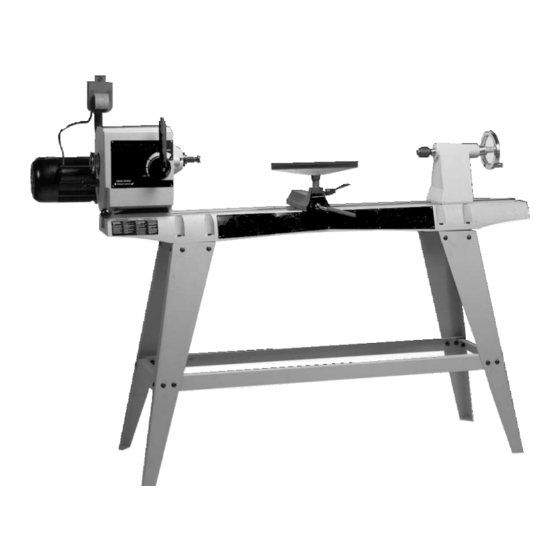
- Page 1 14" Variable Speed Wood Lathe JIB W0903X...
- Page 2 GENERAL SAFETY RULES Woodworking can be dangerous if safe and proper operating procedures are not followed. As with all machinery, there are certain hazards involved with the operation of the product. Using the machine with respect and caution will con- siderably lessen the possibility of personal injury.
- Page 3 ADDITIONAL SAFETY RULES FOR WOOD LATHES WARNING: DO NOT OPERATE THIS TOOL UNTIL 18. TIGHTEN ALL CLAMP LOCKING HANDLES before it is completely assembled and installed according to the operating. instructions. 19. EXAMINE THE WORKPIECE FOR FLAWS and test OBTAIN ADVICE from your supervisor, instructor or glue joints before placing the workpiece in tool.
-
Page 4: Table Of Contents
UNPACKING AND CLEANING Carefully unpack the tool and all loose items from the shipping container(s). Remove the protective coating from all unpainted surfaces. This coating may be removed with a soft cloth moistened with kerosene (do not use acetone, gasoline or lacquer thinner for this purpose). After cleaning, cover the unpainted surfaces with a good quality paste wax. WARNING: FOR YOUR OWN SAFETY, DO NOT CONNECT THE TOOL TO THE POWER SOURCE UNTIL THE TOOL IS COMPLETELY ASSEMBLED, AND YOU READ AND UNDERSTAND THE ENTIRE OWNER’S MANUAL. -
Page 5: Fig. 3
ASSEMBLY INSTRUCTIONS ASSEMBLING STAND (OPTIONAL) Attach the two long tie bars (A) Fig. 3 (with flanges up) to the center of each stand leg (B) by using eight carriage bolts through the legs and tie bars, secured by flat wash- ers, lockwashers, and hex nuts. -
Page 6: Fig. 13
CAUTION: The lathe bed is heavy. Have someone help lift it on the stand. Position the lathe bed so that the holes in the lathe bed are directly above the holes in the stand. Secure the lathe bed to the stand using the eight M8 x 35mm Hex head screws (A) Fig. - Page 7 TOOL REST To position the tool rest on the lathe bed, lift up clamp handle (C) Fig. 17, move the tool rest base to the desired position and lock in place by pushing down on handle (C). To adjust the tool rest (A) Fig. 17 to the correct height, loosen locking lever (D), move tool rest (A) up or down and tighten locking lever (D) The 46-715 has a unique feature in this tool rest.
- Page 8 STARTING AND STOPPING THE TOOL The switch (A) Fig. 21 provides electrical power to the tool. To start the tool, lift the safety cover (B) and lift the switch to the “ON” position. To stop the tool, push the safety cover (B) down. NOTE: IN CASE OF EMERGENCY, IMMEDIATELY PUSH THE SAFETY COVER (B) DOWN TO SHUT OFF POWER.
- Page 9 OPERATION The following directions will give the inexperienced operator a beginning point for common lathe operations. Practice on scrap material before attempting serious work. LATHE TOOLS Standard wood turning tools come in several different configurations (Fig. 26). The majority of turnings will require the gouge tool (A) Fig.
- Page 10 After marking each end, mark the true center with a punch awl or dividers (Fig. 29). If the stock is hardwood, the centers should be drilled to a depth of about 1/8". The spur or live center is then placed against one end of the work and seated by striking with a mallet (Fig.
- Page 11 ROUGHING A CYLINDER The large gouge is used in the first turning operation by smoothing the sharp corners of the work. Run the lathe at low speed and hold the gouge in the manner shown in Fig. 33 The cut starts about 2 inches from the tailstock end and continues from this point to the end of the tail- stock.
- Page 12 SMOOTHING A CYLINDER To smooth a cylinder, use a large skew chisel. This requires practice, but experience with this tool is very important. Place the cutting point near the center of the chisel and high on the work (Fig. 38). Sometimes, in striv- ing for a certain position in relation to the work, the beginner will often overlook this all-important point.
- Page 13 CUTTING A SHOULDER Use the parting tool first to reduce the wood to within 1/16" of the required shoulder and diameter (Fig. 43). Clean the waste stock out with the gouge (Fig. 44), then use the skew for the actual cutting of the shoulder (Fig. 45), which is a duplication of squaring an end.
- Page 14 VEE GROOVES Cutting the vee groove demands much the same technique as the bead, except the skew is hinged straight into the work without rotation (Fig. 51). Only one-half of the vee is made at a time, and one, two, or more cuts may be needed on each side to obtain the desired shape.
- Page 15 The gouge is placed on edge on the tool rest so that the grind of the chisel forms an approximate right angle with the work (Figs. 57). The chisel contacts the work at the center of the cutting edge. Hold the tool so that the centerline of the gouge is pointing directly toward the center of the revolving stock.
- Page 16 FACEPLATE TURNING Mount turnings that cannot be worked between centers on a faceplate. The greater part of this type of turning is done with the faceplate mounting, although there are a number of jobs which require special chucks. All cutting in faceplate work is done by scraping. Any attempt to use a cutting technique on the edge grain of large work will result in a hogging, gouging cut which may jerk the chisel out of the hands of the operator.
- Page 17 The tool rest with the auxiliary extension can be placed in several different angles and positions. Select the one best suited for your work. Fig. 67 shows the position normally used for bowls and other outboard turnings. To move the tool rest on the bed, loosen the handle (A) Fig.
- Page 18 MAINTENANCE REPLACING DRIVE BELT Remove the four screws (A) Fig. 71 (three of which are shown) to take the back off of the headstock. Fig. 71 Use a #5 Allen wrench to remove the three screws (A) Fig. 72. Slide the spindle handle out. Pull the spindle lock to the out position (see Fig.
- Page 19 14” WOOD LATHE...
- Page 20 REPLACEMENT PARTS Ref. Ref. Part No. Part No. Description Description 1342455 PAN HD SCREW 901802 FRONT SWITCH BOX 1320101 EXT TOOTH WASHER 1246016 HEX HD SCREW 901741 MOTOR COVER 901800 SWITCH GUARD 901734 EXT RETAINING RING 901801 SWITCH 1243321 HEX SOC SET SCREW 901811 POWER CORD 909945...
-
Page 21: Flat Washers
OPEN STAND (OPTIONAL) Ref. Part No. Description 1246093 SCREW-HEX HD 901813 BED MOUNTING PLATE 1243526 FLAT WASHER 1246157 LOCK WASHER 1243398 HEX NUT 1349177 CARRIAGE HD SCREW 901812 901814 SHORT BRACKET 901816 LONG BRACKET 903746 903745 STAND HARDWARE PACK...
Need help?
Do you have a question about the JIB W0903X and is the answer not in the manual?
Questions and answers