Table of Contents
Advertisement
Advertisement
Table of Contents

Related Manuals for HARVEY T-60S


Summary of Contents for HARVEY T-60S
- Page 1 INSTRUCTION MANUAL Operation Instructions Wood Lathe Model: T-60S...
-
Page 2: Table Of Contents
Contents Appreciation Letter To Users......................2 Limited Warranty..........................3 General Safety Rules........................4 Introduction............................5 Features............................5 Features Identification........................6 Optional Accessories........................6 Specifications..........................7 Power Supply..........................7 Assembling and Adjustment.......................8 Base............................8 Unpacking..........................8 Packing Contents........................8 Legs Installation........................9 Tool Storage Bracket......................9 Comparator Brackets......................10 Spindle Shield........................ -
Page 3: Appreciation Letter To Users
Today, we offer high-performance machines with innovative solutions that meet the needs of woodworkers and their ever-evolving craft. We appreciate your business and thank you again for becoming a part of the Harvey Industries family. -
Page 4: Limited Warranty
For any parts determined by Harvey Industries Co., Ltd. to be a manufacturer’s defect, we will repair or replace at no charge. We require the defective item/part be returned to Harvey Industries. In the event... -
Page 5: General Safety Rules
General Safety Rules Please operate the lathe with awareness of the potential for injury. If you have any doubts about safety, please contact your local dealer before using. Warning! Failure to follow the listed rules may result in serious personal injury. TO ENSURE SAFE USE, READ THIS MANUAL BEFORE OPERATING THE TOOL. -
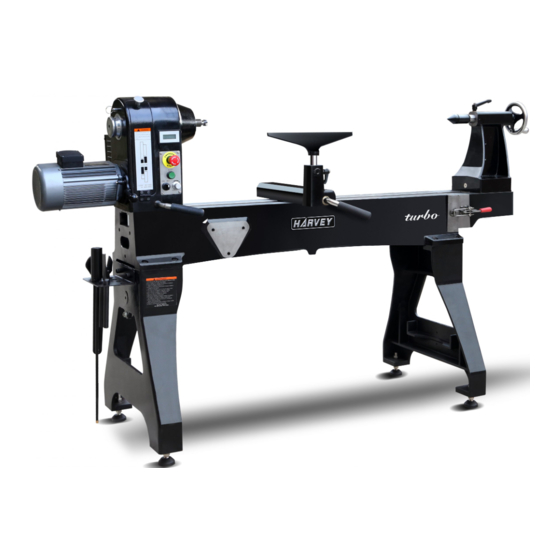
Page 6: Introduction
Introduction Turbo lathes are designed and built to satisfy the most imaginative fantasies of woodworkers. With outstanding new features, superior performances and so many user- friendly considerations, Turbo lathes make turning an unprecedented experience. Features > High grade cast iron structure for headstock beds and stands to secure maximum stability >... -
Page 7: Features Identification
Features Identification A: Motor L:Tail stock B: Belt Access Door M:Tail stock Hand Wheel C: Head stock N:Tail stock Lock Lever D: Face Plate O:12” Swing Away Extension Bed E: Spur Center P:Bed Lock Assembly F: Tool Rest Lock Handle Q:Leg G: Tool Support R:Bed... -
Page 8: Specifications
Specifications Models T-60S Operation Information Swing Over Bed 24” Dist. Between Centers 48” Swing Over Tool Rest Base 20” Spindle Speeds: High Range 200-3500rpm(Variable) Low Range 60-1000rpm (Variable) Floor to Spindle Center Height 44” (NO Leveler ) Headstock Travel Full Length Max. -
Page 9: Assembling And Adjustment
Assembling and Adjustment Warning: The lathe must be powered off during assembly, adjustment or maintenance. Base A level concrete floor is the best location for the lathe. The lathe should be located in a dry area. Keep the electrical box and motor away from direct sunshine. Plenty of space around the lathe is good for operations and maintenance. -
Page 10: Legs Installation
Legs Installation (Refer to Fig. 2) 1. Lift the lathe off the pallet by using a hoist or forklift. Place it on a table or workbench with sufficient clearance which allows for the support legs to be attached from underneath. 2. -
Page 11: Comparator Brackets
Comparator Brackets (Refer to Fig.4) Mount the front comparator bracket (C) to the back of the headstock with two M12 socket head cap screws (D). This bracket can be also used for mounting the spindle shield. Mount the rear comparator bracket (A) to the back of the tailstock. The bracket has a slot so it can be aligned with the front comparator bracket. -
Page 12: 12" Swing Away Extension Bed
12” Swing Away Extension Bed (Refer to Fig. 6) To mount the 12” Swing Away Extension Bed (A), you need to attach the hinge (C) to the hinge axis(B). Fig. 6... -
Page 13: 20" Extension Bed (Optional)
20” Extension Bed (Optional) Refer to Fig.7 -Fig.9 The optional 20” extension bed can be mounted on the lathe in three locations: A: Right end of bed (as shown in Fig. 7) for up to 56” center distance. Fig. 7 B: Right leg (as shown in Fig.8) for outboard turning. -
Page 14: Operation
Operation Notice: The lathe must be powered off during assembly, adjustment or maintenance. Please start the lathe by using the lowest speed! Control Panel Refer to Fig. 10 Fig.10 1. Emergency Stop Button ---Button A: 2. Start/Stop Button ---Button B: Turns the lathe ON or OFF. -
Page 15: Speed Range Adjustment
Speed Range Adjustment (Refer to Fig. 11) The lathe is designed having two speed ranges: Low Range: 60-1000 rpm and High Range: 2000-3500 rpm. In each range, the speed can be changed variably by the electronic variable speed controller. Follow the steps below to change the speed range: 1. -
Page 16: Tool Rest Base (Banjo)
Tool Rest Base (Banjo) The Banjo is designed with a cam-lock system, it can slide along the bed freely when unlocked. Loosen the locking handle and move the Banjo to the desired place. Lock the lever firmly after adjustment Tool Rest The 14″... -
Page 17: Face Plate Installation And Removing
Face Plate Installation and Removing (Refer to Fig. 13) 1. Unplug the lathe from the power source. 2. Mount the face plate to the work piece. 3. Install the face plate onto the spindle thread and turn it clockwise 4. Insert the lock rod (A) into the hand wheel hole. Hold the rod and tighten the face plate with the face plate wrench (B). -
Page 18: General Maintenance
General Maintenance Daily: Wipe off the dust from the lathe with a soft bench brush. Apply a coat of wax on the Spindle, Tail Stock Quill and bed. Monthly: Check the belt tension. Check the belt for wear and tear and change the worn and torn belt. Clean the dust from the belt. -
Page 19: Trouble Shooting
Tighten lock handle. loose. Lathe on uneven surface. Adjust leveling feet. Driver is not programmed Lathe runs at one Contact Harvey Technical Service properly, or is defective, or speed only. to help identify problem. there is loose wiring. Dull tools. -
Page 20: Wiring Diagram
Wiring Diagram... -
Page 21: Inspection Certificate
INSPECTION STANDARDS (Wood Lathe) This machine is inspected in the factory and meets the following precision standards. Standard Index Diagram Inspection Item (mm) 0.08/800 a: Straightness b: Parallelism 0.02 Spindle radial runout. 0.01 Spindle end-face runout. 0.01 0.01 a: Spindle inner taper runout. b: Spindle near thread test rodrunout.. -
Page 22: Exploded View And Parts List
Exploded View and Parts List Head Stock Assembly 113 114 109 110 131 132 DESCRIPTION DESCRIPTION REF# REF# Position Pin Position Block Position Pin Label Taper Pin Hex Socket Cap screw M4×12 Round Head screw Magnet Lock Shaft Hex Nut M4 Clamp Block Headstock Casting Lock Nut M20... - Page 23 Tail Stock Assembly DESCRIPTION DESCRIPTION REF# REF# Adjusting Handle M10×45 Position Block Lock Block Position Pin M6-¢5 Tail Stock Position Block Sleeve Taper Pin Lead Screw Round Head screw Position Ring Lock Shaft Washer Clamp Block Set Screw M8×10 Lock Nut M20 Hand Wheel Rubber Sleeve ¢21.5×120×δ3 Handle...
- Page 24 Tool Rest Assembly 3 0 1 3 0 2 3 0 3 3 0 4 3 0 2 3 0 5 1 2 0 3 0 6 1 2 5 1 3 9 1 2 6 1 2 8 DESCRIPTION DESCRIPTION REF# REF#...
- Page 25 Motor Assembly 416-1 416-1 405 404 416-2 440-2 421 422 440-1 DESCRIPTION DESCRIPTION REF# REF# Three-position Switch Cap Screw M5×12 C3SS1-10B-20 Spring Washer 5 2HP AC Induction Motor Magnet D8×5 Adjusting Handle M10×20 Switch Flat Washer 10 Switch Bracket Motor Flange Cover Handle Ball M10×32 Cap screw M5×12...
- Page 26 Electric Assembly 507 508 DESCRIPTION DESCRIPTION REF# REF# Baffle Cable lock KVT 32 A Partition Backing Plate Connector Electrical Box Relay Start Button Fixator Driver ASD-B2-1521-B Terminal Plate Button Head Screw M4×8 Main Power Switch Spring Washer 4 Bottom of box Flat Washer 4 Window Card Slot...
- Page 27 Bed Assembly DESCRIPTION DESCRIPTION REF# REF# Stand Hex Socket Cap screw M12×35 Leveler M16×65 Position Pin...
- Page 28 Swing Extension Assembly 531 530 547-1 547-2 DESCRIPTION DESCRIPTION REF# REF# Cap screw M8×25 Magnet Set Screw M6×10 Locating Shaft Hinge Shaft Flat Washer 12 Brass Sleeve Spring Washer 12 Lower Hinge Cap screw M12×20 Upper Hinge Cap screw M12×50 Swing Extension Bed 12”...
Need help?
Do you have a question about the T-60S and is the answer not in the manual?
Questions and answers