
Subscribe to Our Youtube Channel
Related Manuals for HARVEY T-40


Summary of Contents for HARVEY T-40
- Page 1 Revision A (2020-03-01) INSTRUCTION MANUAL Operation Instructions Turbo Woodworking Lathe Model: T-40...
-
Page 3: Table Of Contents
Contents General Safety Rules ......................2 Introductions ........................3 Features ..........................3 Features Identification ...................... 4 Optional Accessories ......................4 Specifications ........................5 Power Supply ........................5 Assembling and Adjustment .................... 6 Base ..........................6 Unpacking ........................6 Packing List ........................ 6 Operatings .......................... -
Page 4: General Safety Rules
General Safety Rules Please operate the lathe with awareness of the potential for injury. If you have any doubts about safety, please contact your local dealer before using. Warning! Failure to follow the listed rules may result in serious personal injury. TO ENSURE SAFE USE, READ THIS MANUAL BEFORE OPERATING THE TOOL. -
Page 5: Introductions
The Turbo T-40 lathe is crafted with premium grade cast iron and machined to the highest tolerances. The guideways are precision ground for smooth operation. The surface of the T-40 lathe is coated with a high gloss, stoved varnish. -
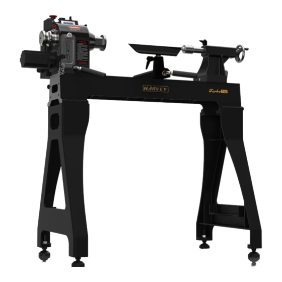
Page 6: Features Identification
Feature Identification Identification Figure 1 Servo Motor Tail Stock Spindle Hand Wheel Spindle Hand Wheel Tail Stock Hand Wheel Tail Stock Hand Wheel Driver Tail Stock Locking Handle Tail Stock Locking Handle Control Buttons Control Buttons Speed Display Tool Slide Head Stock Tool Rest Locking Handle Tool Rest Locking Handle... -
Page 7: Specifications
Specifications Market North American European Asian Maximum Swing Over Bed 14″ (360mm) 360mm 360mm Distance Between Centers 24″ (610mm) 610mm 610mm Max. Swing Over Tool Slide 10″ (260mm) 260mm 260mm Basic Specification High Range 90-4300 rpm 90-4300 rpm 90-4300 rpm Spindle Speeds: Low Range... -
Page 8: Assembling And Adjustment
Assembling and Adjustment Assembling and Adjustment Base The lathe must be placed on a flat, dry surface. The electricity components must not be The lathe must be placed on a flat, dry surface. The electricity components must not be The lathe must be placed on a flat, dry surface. The electricity components must not be exposed to direct sunlight. -
Page 9: Operatings
Operating Notice: The lathe must be powered off during assembly, adjustment or maintenance. Please start the lathe by using the lowest speed! Control Panel Figure 3 1. Emergency Stop Button—Red Button A: If you stop the lathe by pressing the red button “A”, when restarting the lathe, you need to turn the switch “C”... -
Page 10: Speed Range Adjustment
Speed Range Adjustment Figure 4 The lathe is designed having two speed ranges: Low Range: 60-2800rpm and High Range: 90-4300rpm In each speed range, the Speed Adjustment Knob can change the spindle speed freely. Follow the steps below to change the speed range: 1. -
Page 11: Tool Slide
Tool Slide The Tool Slide is designed with a camshaft locking system. It can be moved along the bed smoothly. Pull up the Tool Slide Locking Handle in order to move the Tool Slide to any position, then tighten by pressing down the Tool Slide Locking Handle. Tool Rest The 12”... -
Page 12: Using The Spur Center
Using the Spur Center (Figure 6) 1. Make sure the lathe has been turned off. 2. Make sure the Spur Center taper and the Spindle hole are clean, then push the Spur Center into the Spindle hole. 3. To remove the spur center, place the Knockout Rod in the center of the Hand Wheel and strike the Spur Center until the Spur Center is disengaged. -
Page 13: Trouble Shooting
Trouble Shooting Trouble Probable Cause Remedy Check power supply, lead No incoming power. connections Lathe won’t start. Contact Harvey Technical Problem with driver. Service. Undersized wires in power Increase supply wire size. supply system. Motor fails to develop full Contact Harvey Technical Faulty driver. -
Page 14: Wiring Diagram
Wiring Diagram... -
Page 15: Inspection Certificate
INSPECTION STANDARDS (Wood Lathe) This machine is inspected in the factory andmeets the following precision standards. Standard Index Diagram Inspection Item (mm) 0.08/800 a: Straightness 0.02 b: Parallelism Spindle radial runout. 0.01 Spindle end-face runout. 0.01 a: Spindle inner taper runout. 0.01 b: Spindle near thread test 0.015... -
Page 16: Exploded View And Parts List
Exploded View and Parts List Exploded View and Parts List Head Head Stock & Bed Assembly REF# DESCRIPTION REF# DESCRIPTION Head Stock Adjusting Head Stock Adjusting Stop Rod Ball Bronze Sleeve Bearing Bronze Sleeve Bearing Spring Tension Washer Hex Lock Nut M12 Index Pin Strong Magnet Spindle Hand Wheel... - Page 17 Tail Stock Assembly REF# DESCRIPTION DESCRIPTION REF# DESCRIPTION Hex Lock Nut M12 Hex Lock Nut M12 Tail Stock Lock Handle Tail Stock Lock Handle Tail Stock Quill Tail Stock Quill Jump Ring 14″Tail Stock Tail Stock Position Piece Tail Stock Position Piece Tail Stock Quill Tail Stock Quill Sleeve Cap Screw M6×16...
- Page 18 Tool Rest Assembly REF# DESCRIPTION DESCRIPTION REF# DESCRIPTION Hex Lock Nut M12 Hex Lock Nut M12 Tool Rest Copper Washer Tool Rest Copper Washer M6-Ф5 Position Pin Ф5 Position Pin Tools Rest Lock Handle Lock Handle Rubber Grip Tool Slide Copper Blot Tool Slide Copper Blot Lock Piece Tool Slide Lock Handle...
- Page 19 Motor and Electric Assembly Description Description Description Set Screw M6×6 Speed Adjust Knob Terminals 14″Head Stock Case Set Screw M4×5 Cap Screw M4×12 Cap Screw M6×12 Position Bar Connection Nut Servo Motor Speed Display Connection Nut Flat Key Electricity Case Electricity Side Cover Handle M8×25 Three-Position Switch...
Need help?
Do you have a question about the T-40 and is the answer not in the manual?
Questions and answers