
Summary of Contents for Pyramid 5 KW 3 Phase
- Page 1 An ISO 9001 Certified Company THREE PHASE GRID TIED SOLAR INVERTER User & Installation Manual for 5 KW 3 Phase Solar Inverter to be connected to the Utility Grid in India 2021...
-
Page 2: Table Of Contents
10.3 Setting Up Restart Timer ........11 Technical Data © Pyramid Electronics... - Page 3 5KW 3-Phase Grid Tied Solar Inverter USER MANUAL 5 KW THREE PHASE GRID-TIED SOLAR INVERTER © Pyramid Electronics...
-
Page 4: Introduction
Environment temperature affects the power output of PV modules. Higher the temperature, lower the power output of PV module. Comparing the pole-mounted PV array, roof-mounted PV module array generates less power due to less air circulation and and excessive heat from the roof top. © Pyramid Electronics... -
Page 5: Angle Of The Sun
Caution identifies conditions or practices that could result in damaged to the unit or other equipment connected. WARNING! Before installing and using this inverter, read all instructions and cautionary markings on the inverter and all appropriate sections of this guide. © Pyramid Electronics... - Page 6 ) and can cause a serious injury. CAUTION! Do not operate the Inverter if it has received a sharp blow, been dropped, or otherwise damaged in any way. If the Inverter is damaged, please contact the system installer. © Pyramid Electronics...
-
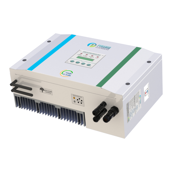
Page 7: Unpacking & Overview
CAUTION! Make sure that the earth wire of the inverter is properly earthed to reduce the risk of electric shock. Unpacking & Overview Packing List Before installation, please inspect the unit. Be sure that nothing inside the package is damaged. The following items must be present inside the package: Product Overview © Pyramid Electronics... -
Page 8: Installation Procedure
1. Employ the wall mounting plate as a template for marking the positions of the boreholes on the wall. 2. Mount the wall mounting plate with appropriate screws (M5,SUS304) into four holes to fix the mounting plate on the wall. © Pyramid Electronics... - Page 9 4. After final fixing the solar inverter on wall mounting plate, it will look like as shown in the below figure. Note: If two or more solar inverters need to be installed in close proximity, then there should be a distance of at-least 1 m between any two inverters. © Pyramid Electronics...
-
Page 10: Grid, Pv And Antennas Connection
Table 1: Suggested cable requirement for grid side wire (Phase, Neutral and Earth) Model Conductor Cross-Section 5 KW 3 Phase 5.1.2 Connection to AC Utility WARNING!! To prevent risk of electric shock, ensure the earth terminal of the solar inverter is properly earthed before operating the solar inverter. - Page 11 ˆ Strip cables, only multiple strands of copper wire can be used. Please cut and strip the wire according to the requirements, and the ground wire needs to be 5 mm longer than live and neutral wire, and the applicable stripping length is 7-8 mm. © Pyramid Electronics...
- Page 12 ˆ Now three phase 5 wire cable has to be connected to the female part of connector shown below. ˆ Install the cable gland and connector body to the cable. ˆ Strip the cable outer jacket, trim and strip each insulation, then solder the female contact pin on each conductors as shown in figure. © Pyramid Electronics...
-
Page 13: Solar (Dc) Connection
100 V DC - 1000 V DC. This system has a single input, please make sure that the maximum current of PV input connector is less than or equal to 17 A for present 5 KW 3 Phase Grid Tied Solar Inverter. - Page 14 Table 2: Suggested cable requirement for DC wire (PV+ and PV-) Model Conductor Cross-Section 5 KW 3 Phase CAUTION: Never directly touch terminals of the inverter. It will cause lethal electric shock. Outline size of MC4 Solar connector ˆ...
- Page 15 first, you will not be able to get the plastic housing off without damaging it and rendering it. ˆ Insert the cable. ˆ When you push the crimped cable into the connector, you will hear a ‘CLICK’. This is the non return clip locking the crimp into the plastic housing. © Pyramid Electronics...
- Page 16 15 mm to expose the wire for crimping as done in above steps. ˆ Insert the cable. ˆ Again pass the screw nut over the cable first. Check the rubber washer as in above step and push the crimped cable into the female housing until you hear the ’CLICK’. © Pyramid Electronics...
-
Page 17: Gsm / Wifi Connection
Connect the two antennas provided in the packaging box. Only tighten the antennas to the screw provided on solar inverter body. The inverter has built-in GSM (SIM) and WiFi and can be connected to the internet for remote monitoring. © Pyramid Electronics... -
Page 18: Turning The Inverter On
ˆ The GSM module inside the inverter is already activated, provided the user has paid for the GSM postpaid SIM. ˆ When inverter turns ON, it will try to connect automatically to the server (provided that SIM network is available). © Pyramid Electronics... - Page 19 – To enter the password, keep the “ Up” button pressed till the character “1” is reached. – Press Enter and then the second character is to be entered (that is “2”). – Continuing the same way, user needs to enter all the characters of the password (maximum of 32 characters are allowed). © Pyramid Electronics...
-
Page 20: Remote Monitoring Using Web App
ˆ It will open the home page on screen as shown below. ˆ Now click on ‘SignUp Now’ and a new page will appear on screen as shown below. ˆ Enter all the details and click on ‘Register’ button. © Pyramid Electronics... - Page 21 ˆ When inverter is added successfully, login with your credentials (Username and Password) from the same home page. ˆ After login on home page, it will open the ‘Dashboard’ screen as shown below. © Pyramid Electronics...
- Page 22 ˆ To check on information related to inverters associated with a particular user ID, the user can click on ‘Inverter’ tab given on side bar navigation, which further contains the following options:- 1. To add any other inverter, click on ‘Add Inverter’ option. The screen will open as shown below. © Pyramid Electronics...
- Page 23 2. To get the details of registered inverters, click on ‘Registered Inverters’. The screen will open as shown below. 3. To check the warranty of inverters, click on ‘Check Warranty’. The screen will open as shown below. © Pyramid Electronics...
- Page 24 ˆ To get the current status of the tickets, click on ‘View Tickets’. The screen will open as shown below. ˆ To report any issues related to inverter, click on ‘Report Issue’ option. The screen will open as shown below. © Pyramid Electronics...
- Page 25 ˆ Enter the ‘Serial Number’, ‘Title’ and ‘Description’ for the inverter and click on ‘Report’ button. ˆ To check the personal details, click on ‘User Profile’. The screen will open as shown below. ˆ Click on ‘About Us’ option to get brief description about Pyramid Electronics. The screen will open as shown below.
-
Page 26: Remote Monitoring Using Mobile App
‘Android’ (Play Store) or Iphone (App Store) and hit enter. ˆ After the application is successfully installed, user can open the application and screen shown below will appear. ˆ Click on ‘Sign Up’ button to register as shown below. © Pyramid Electronics... - Page 27 ˆ User can login by requesting OTP (‘Login with OTP’) or entering password with ‘Login with Password’ option as shown below. ˆ In case user forgets his/her password, he/she can click on ‘Forgot Password’ button and change it by using registered contact number as shown below. © Pyramid Electronics...
- Page 28 ˆ OTP will be sent to the registered contact number. Enter the OTP and click on ‘Confirm’ button to add the inverter. ˆ Once the inverter is linked, user can check energy generated by the solar inverter on daily, monthly and yearly basis on the ‘Dashboard’ as shown below. © Pyramid Electronics...
- Page 29 ˆ User can also edit his/her inverter’s name or delete his/her inverter from his/her account. To go back, user can click on back button on top left corner of the screen. . ˆ To get the current status of tickets, click on ‘Tickets’ tab, screen will open as shown below. © Pyramid Electronics...
- Page 30 ˆ Select the inverter, enter the ‘Serial Number’, ‘Title’ and ‘Description’ of the issue and click on ‘Report’ button. ˆ To get the inverters list, click on ‘Inverters’ tab in bottom left corner. The inverters screen will appear as shown below. © Pyramid Electronics...
- Page 31 ˆ User can add new inverter by clicking on plus ‘+’ icon on top right corner on the screen. ˆ Check the personal details by clicking on ‘Setting’ icon on top left corner of the screen. ˆ User can check warranty for all inverters in ‘Warranty’ section. © Pyramid Electronics...
- Page 32 5KW 3-Phase Grid Tied Solar Inverter ˆ User can also choose between ‘Light’ and ‘Dark’ theme for the application as shown below. ˆ User can click on ‘About’ to get brief description about ‘Pyramid Electronics’. The screen will open as shown below.
-
Page 33: Maintenance And Cleaning
ˆ Please do not separate and mate the connector system unnecessarily unless it is for repairing or maintenance purposes, as it may reduce the waterproof performance of the system. WARNING!! Remember that this inverter weighs around 16 kgs! Please be careful when lifting it out of the package. © Pyramid Electronics... -
Page 34: Trouble Shooting
3. If the fault is still present, please contact on +91- 7087432486. Low PV Power 1. The fault is detected if PV power is less than 100 Inverter Off 2. If there seems to be enough sunlight, and inverter still does not work please contact on +91-7087432486. © Pyramid Electronics... -
Page 35: User Interface
2020 till 2030. So, there is provision for the user to view daily, monthly or yearly energy data user © Pyramid Electronics... - Page 36 5KW 3-Phase Grid Tied Solar Inverter Figure 3: User Interface: Keypad and LCD Display © Pyramid Electronics...
-
Page 37: Setting Up Inverter Modes
Enter and UPF mode will be set and “Unity Power Mode Set” will be displayed on screen and the inverter enters the default loop (Figure 2 on page 34). To set FPF mode, press Up/down keys when “Unity Power Factor Mode?” is displayed on the screen © Pyramid Electronics... -
Page 38: Setting Up Restart Timer
Display Unit in default loop. For this, follow the path shown in flowchart (Figure 3 on page 35) and reach “Measurements ?”. With “Measurements?” displayed on the LCD Display, press Enter button. The Display unit then goes into the default loop (see Figure 2 on page 34). © Pyramid Electronics... -
Page 39: Technical Data
IS 1622 / IEC 62109-2 Anti-islanding IS 16169 / IEC 62116 Harmonic Current Control IEC 61000-3-2 Grid Under/Over Voltage Setting as per CEA India by default (settable upto 180 V (per phase) Grid Under/Over Frequency Setting as per CEA India © Pyramid Electronics...
Need help?
Do you have a question about the 5 KW 3 Phase and is the answer not in the manual?
Questions and answers