Table of Contents
Advertisement
Quick Links
Advertisement
Table of Contents

Related Manuals for Gent 800


Summary of Contents for Gent 800
- Page 1 Operator’s Manual & Log book System 800 Fire Alarm Panel...
-
Page 2: Table Of Contents
Table of Contents Scope General description User responsibility Daily Weekly Quarterly Battery replacement Controls and indicators Navigation Access levels To enter access level 2 To return to access level 1 Normal Condition To conduct a display test Fire condition To verify fire To cancel buzzer To silence alarms To reset the system... - Page 3 Fire routing output Fault routing output Maintenance reminder Appendix Glossary of terms Log Book Description of controls and indicators Controls at the system 800 panel Indicators at the system 800 panel Menu Controls and indicators 796689 (4188-658) _ I1.1 /02.01...
-
Page 4: Scope
Scope This first issue of the Operator’s manual covers the operating instructions for the 24- zone system 800 fire alarm panel. The manual shows how to operate controls and interpret light indications and messages. It includes user responsibility and emergency conditions with step by step instructions on how to operate controls. -
Page 5: General Description
General description The system 800 fire alarm panel is designed to meet the requirements of EN54 Parts 2 and 4. It is suitable for installation in small to medium size buildings in accordance with the recommendations of BS5839:Part 1, to provide an automatic fire detection and alarm. -
Page 6: User Responsibility
It is recommended that the persons User responsible for the fire alarm system should responsibility become familiar with: How to operate the controls How to interpret visual indications given. Daily BS 5839:Part 1, states that the system should be inspected daily to ensure that a normal indication is given at the control and indicating equipment and: any previously indicated fault and... -
Page 7: Quarterly
Servicing organisation, see log book. Battery replacement Every four years the batteries installed in the system 800 panel must be replaced. CAUTION: RISK OF EXPLOSION IF BATTERY IS REPLACED BY AN INCORRECT TYPE. DISPOSE OF USED BATTERIES ACCORDING TO THE INSTRUCTIONS. -
Page 8: Controls And Indicators
While reading the instructions it may help to Controls and open out the back page of this manual to indicators view the location of controls and indicators on the panel, for description of controls and indicators see User controls and indicators section. -
Page 9: Access Levels
The instructions in this manual are for Access levels access to menu options and push button controls available at access levels 1 and 2. (A1) Access level 1 Access level 1 is for the general public and requires no coded entry, and at this level the light indications of the panel are visible, along with menu options to view logs and gain coded entry to level 2. -
Page 10: To Return To Access Level
To return to access To exit access level 2 and return to access level 1. level 1 Press the Esc button to exit to level 1. Press Enter to accept a return to level 1 and the display will respond with the access level changed message. -
Page 11: Normal Condition
Normal Condition The green LED is normally lit giving a steady Power indication to indicate mains and battery supply to the panel are healthy. To conduct a display The panel lights and display can be tested to test check they are working. The Display Test is factory set to operate at access level 2. -
Page 12: Fire Condition
Fire event(s) from detectors or manual call Fire condition points in zone(s) are indicated and logged at the panel. The red Fire light is lit. Fire N um ber of First fire : D evice or location labe l zones in fire Zo ne num ber Latest fire N um ber of... -
Page 13: To Verify Fire
To verify fire If delay mode is ON, that is if the Delay light is lit, the alarm sounders are inactive for a 30 seconds duration. During this time the alarm Delay delay can be extended by a pre-configured time (up to 10 minutes maximum) by operating the Verify button. -
Page 14: Manual Control Of Fire Alarms
Manual control of fire alarms To sound alarms To manually sound alarms in the system at anytime or resound the alarms after they have been silenced: Enter access level 2. Sound Alarms Press the Sound Alarms button. Note the alarms are sounding! To silence alarms To stop the alarms from sounding: Enter access level 2. -
Page 15: To Operate Delay Mode
The Delay Mode (also called Day mode) To operate facility allows the panel to delay the fire delay mode alarms from sounding in the event of a fire. With the Delay mode active there is an initial 30 seconds delay before alarms are made active in the event of a fire. -
Page 16: Fire Test
The system 800 panel has a fire test facility, Fire Test which puts all the zones into test mode and recommends which manual call point is to be fire tested next. In Test State all normal fire detection functions are disabled. -
Page 17: To Exit Fire Test Mode
To exit Fire test After the fire test on manual call point is complete the panel must be taken out of the mode test mode and returned to normal operating condition. In Test State all normal fire detection functions are disabled. Enter access level 2. -
Page 18: Fault Condition
A fault condition is an automatic detection of Fault condition faults in the system requiring attention. A fault detected in the fire alarm system is given at the panel in the form of light indication(s) and text message(s) on the display, accompanied with an audible sound from the local buzzer. - Page 19 typical Light indication message(s) Meaning Mains supply The mains or back Fault failed up battery supply to the panel has failed. Power Fault Battery disconnected. Master alarm 1 There is an open or Fault / 2 open / short circuit fault on short the master alarm sounder circuit 1 or...
-
Page 20: Disablement Condition
A disablement condition is usually a Disablement manual action using the controls at the condition panel to disable parts of the system. Any service and maintenance work on the panel or system must be carried out by a trained maintenance engineer from the fire alarm servicing organisation. -
Page 21: System Information
System information The fire log shows all current fires detected To view active fire in the system, which can be viewed at any events time during the fire condition. Press Enter to display the top-level menu. From the Logs menu select Active fire option and press Enter to accept the selection. -
Page 22: To View Active Disablement
The disablement log shows all current To view active disablements in the system, which can be disablement viewed at any time during disablement condition. Press Enter to display the top-level menu. From the Logs menu select Disablement option and press Enter to accept the selection. -
Page 23: System Set Up
System set up Only a trained person must attempt any changes to the Hardware link hardware link. When making changes to the panel set up the modified data must be saved to the EEPROM. To save the data to the EEPROM a hardware link located on the electronic module inside the panel must be configured. -
Page 24: To Enable Or Disable A Zone
A zone is a collection of installed devices in To enable or disable a sub division of the protected building. The a zone detection devices in a zone can be disabled, for example during maintenance work on the system. On completion of maintenance work the zone must be re-enabled. -
Page 25: To Edit A Zone Label
Each zone can have an individual 32 - To edit a zone label character label. A zone label is used to describe the sub division of the protected If the zone label building where there is an event detected. In field is left blank, the event of a fire the zone label is displayed then the device... -
Page 26: To Put A Zone In And Out Of Test Mode
Any zone can be individually put into test To put a zone in and mode to allow the devices in the zone to be out of test mode tested. In test mode the panel will not detect fires from devices in the zone of the protected building. -
Page 27: To View Devices In A Zone
To view devices in a The devices assigned to any zone can be viewed for confirmation. The list will show all zone the devices in the selected zone. Enter access level 2 (A2) and use the navigation buttons to highlight and select options: Previous Next... -
Page 28: To Enable Or Disable A Device
A device such as a detector or manual call To enable or disable point can be disabled or enabled. This may be a device necessary during maintenance work on the system. On completion of maintenance work the device must be re-enabled. Enter access level 2 (A2) and use the navigation buttons to highlight and select options:... -
Page 29: To Edit A Device Label
Each device on the loop can have an To edit a device individual 32 -character label. A device label label is used to describe the location where it is installed in the protected building. In the event of a fire the device label is displayed on the screen. -
Page 30: To Enable Or Disable Alarm Sounders
The alarm sounders of the system can be To enable or disable manually disabled, for example when doing alarm sounders maintenance work on the sounder circuit. On completion of maintenance work the alarms must be re-enabled. Enter access level 2 (A2) and use the navigation buttons to highlight and select options: Previous... -
Page 31: To Set Up Weekly Reminder Of Fire Test
The weekly test reminder can be a custom To set up weekly message that is displayed on the screen. reminder of fire test The message appears automatically on the specified day, to remind persons responsible that a fire test is due. If the reminder is not required then it can be switched Off. -
Page 32: To Set Up The Delay Mode Verify Timeout
To set up the delay The delay mode facility (also called Day mode) provides a delay before sounding mode Verify timeout alarms in the event of a fire. In a fire condition the in the system can be delayed alarm sounders from sounding, providing the Day mode delay set up was pre-set and... -
Page 33: Other Controls
The following functions they are used during Other controls commissioning of the system and are documented here for reference. The loop status function shows the status Loop status of the loop circuit, for example if it is running or has stopped. A running loop implies the loop is operating correctly and requires no intervention, however a stopped loop must be started, using the start detection function. -
Page 34: Auxiliary Relay
The auxiliary relay function configures a Auxiliary relay relay in the panel, which provides changeover contacts for external use. The relay can be configured to operate with fire event (factory default setting), fault event or disablement, or its function can be internally disconnected. -
Page 35: Appendix
Appendix Glossary of terms The definitions of terms given here are in relation to the description of the system 800 Fire alarm panel. Zone – A zone consist of a maximum of 32 devices such as detectors and manual call points in a sub-division of a building, monitored by the system 800 panel. -
Page 36: Log Book
Log Book SITE ADDRESS To comply with the requirements of __________________________________ BS5839:Part 1 and to allow those concerned __________________________________ with the fire detection and alarm system to __________________________________ monitor the long term performance of the __________________________________ system, it is important that a log is kept which Contract No._______________________ include all the events... - Page 37 Event Log Make copies of blank log pages before the logbook becomes full. date date time event action complete name 796689 (4188-658) _ I1.1 /02.01...
- Page 38 Event Log Make copies of blank log pages before the logbook becomes full. date date time event action complete name 796689 (4188-658) _ I1.1 /02.01...
- Page 39 Event Log Make copies of blank log pages before the logbook becomes full. date date time event action complete name 796689 (4188-658) _ I1.1 /02.01...
- Page 40 Event Log Make copies of blank log pages before the logbook becomes full. date date time event action complete name 796689 (4188-658) _ I1.1 /02.01...
- Page 41 Event Log Make copies of blank log pages before the logbook becomes full. date date time event action complete name 796689 (4188-658) _ I1.1 /02.01...
- Page 42 Event Log Make copies of blank log pages before the logbook becomes full. date date time event action complete name 796689 (4188-658) _ I1.1 /02.01...
-
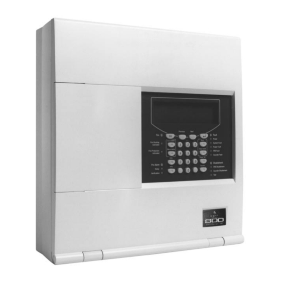
Page 43: Description Of Controls And Indicators
Description of Controls and Indicators A - Flap B - Instructions P re v i o u s N e x t F i re E s c F a u l t P o w er A B C S ou n d A l ar m s D E F R es et... -
Page 44: Controls At The System 800 Panel
Controls at the system 800 panel Access Control Level Function The button starts the alarm sounders Sound Alarms in the system, see page 14. The button stops the alarm sounders Silence Alarms from sounding in the system, see pages 13, 14. -
Page 45: Indicators At The System 800 Panel
These buttons are used to scroll Previous through active event list, form fields and menu options. Next These buttons are used for entering alphanumeric data. Indicators at the system 800 panel label light operation and meaning Fire STEADY – There is one or more (red) fire(s) in the system OFF –... - Page 46 label light operation and meaning Fire Protection STEADY – The fire protection Activated output (fixed extinguishing) is (red) active. OFF – The fire protection output is not active. Pre Alarm Not used at present! (red) STEADY – There is at least one coincidence zone / device in pre- alarm.
- Page 47 label light operation and meaning Power fault STEADY – There is either a mains (yellow) or battery supply fault. OFF – There is no power fault. FRE Fault STEADY – There is a fire routing (yellow) equipment fault. OFF – There is no FRE fault. Sounder Fault STEADY –...
- Page 48 This page has been intentionally left blank. 796689 (4188-658) _ I1.1 /02.01...
-
Page 49: Menu
Menu Controls and indicators Menu map of access levels 1 and 2. Display M en u m ap at A 1 A cce ss lev el 1 (N o cod e re quired) Menu control buttons M en u m ap at A 2 A cce ss lev el 2 (C ode 222 2) Previous Next Fire... - Page 50 This page has been intentionally left blank. 796689 (4188-658) _ I1.1 /02.01...
- Page 52 Gent limited 140 Waterside Road, Hamilton Industrial Park, Leicester LE5 1TN Tel 0116 246 2000 796689 (4188-658)_I1.1 / 02.01...
Need help?
Do you have a question about the 800 and is the answer not in the manual?
Questions and answers