Advertisement
Operating instructions and Log Book
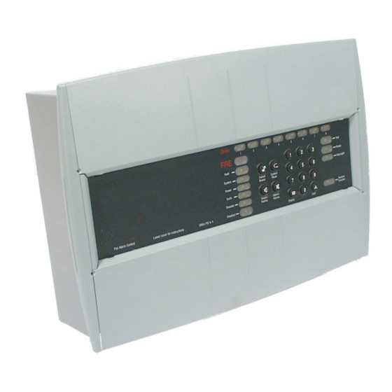
Fire Control and Repeat panels
(Conventional 2, 4 and 8 Zone panel range)
This manual covers the
Operating instructions
and Log book, and is
intended for use by the
End User.
The manual should be
located in a secure but
accessible position close
to the panel.
It is the responsibility of
the End User to maintain
the Log Book.
An Installation and Commissioning
guide has been supplied for your
installer with this panel.
4188-424 issue 8_Part 2_07-14_Xenex
www.acornfiresecurity.com
www.acornfiresecurity.com
Operating instructions
Contents
Page
Operating instructions for AL2
2
3
4
5
7
9
Advertisement

Related Manuals for Gent Xenex 13270-02LB


Summary of Contents for Gent Xenex 13270-02LB
-
Page 1: Table Of Contents
Operating instructions and Log Book www.acornfiresecurity.com Fire Control and Repeat panels (Conventional 2, 4 and 8 Zone panel range) Operating instructions This manual covers the Operating instructions Contents Page and Log book, and is intended for use by the User responsibility End User. -
Page 2: User Responsibility
Fire Panels www.acornfiresecurity.com User responsibility q That no unsafe practices that Your fire alarm system should installed, an in-depth investigation have been designed, installed and could lead to fire are being should be instigated on commissioned to your site specific undertaken. -
Page 3: Testing A Manual Call Point
Fire Panels www.acornfiresecurity.com Testing a Manual Call Point Testing a Manual call point To test a manual call point you will need a call point test key, see instructions supplied with the call point as the procedures may vary dependent on the call point. q Push the test key through the hole in the underside of the call point and release the key to activate the call point. -
Page 4: Control & Indications
Fire Panels www.acornfiresecurity.com Controls and indicators ZONE Fire, Fault or Disablement indications yellow Zones yellow FIRE Test Normally lit Fault green to indicate Power supply Power System healthy yellow Delay Cancel System Power Buzzer Reset yellow yellow Earth Access / Sounder Function Sound... -
Page 5: Operating Instructions
Normal indications Fire Panels www.acornfiresecurity.com Operating instructions Normal indications Under normal condition the panel should give a healthy indication, with only the green Power light lit. The control panel provides system security by password entry to controls. Fire Condition In the event of an automatic fire detection the indications given are: q FIRE light is lit. - Page 6 Fire Panels Indications given of various conditions www.acornfiresecurity.com Indications given of various conditions CONDITIONS Normal Fire New fire Access Function (different level 2, 3 zone) or 4 pressed Visual Zone Fire (1-8) - Red Fire Common Disabled - Yellow Test - Yellow Power - Green Access / Function - Yellow Fast pulse...
- Page 7 Fault Conditions Fire Panels www.acornfiresecurity.com Other Access level 2 operations To carry out a display test q Enter the 3 digit code to gain access to the controls. - Coded entry is only required if Display test function is configured for operation at Access level 2. q Press the ‘shift‘...
- Page 8 Fire Panels Fault Conditions www.acornfiresecurity.com How to disable a zone Disabling a zone will prevent fires being detected in the zone. q Enter the 3 digit code to gain access to the controls. Check that the Access/function lamp is lit. q Press the and 1 buttons followed by the number of the zone to be disabled.
-
Page 9: Log Book
Fire Alarm System Fire Panels www.acornfiresecurity.com Log Book Fire Alarm System In order to satisfy the recommendations of BS 5839 Part 1 there should be a log book to record system events, that is maintained by a responsible person. The following pages provide layout of a log book. Address of protected premises________________________________________________________________ Responsible person:________________________________________________________________________ System designer:__________________________________________________________________________... - Page 10 Fire Panels System configuration record www.acornfiresecurity.com System configuration record Record of how the system is configured. Mark in the table below any deviation(s) from the standard factory settings Detection and zone circuit configuration Zone number Normal zone operation (factory setting) Non latching zone operation First fire to be a pulsing indication (factory setting) First fire to be a steady indication...
- Page 11 Location of system devices Fire Panels www.acornfiresecurity.com Location of system devices Record of devices installed in the system, their locations and zone relationships for reference. Zones Location Type of system device Events Log It is recommended that a Log book is created were a record of system events and work done is kept. Record events other than false alarms and maintenance work.
- Page 12 www.acornfiresecurity.com False Alarms Do not record other events and maintenance work details in this log, see respective sections. # Categories: Unwanted - unwanted false alarm, Equipment - equipment false alarm, Good intent - false alarm with good intent, Malicious - malicious false alarm and Unknown - cause of alarm not known. Time Device Cause (if...
Need help?
Do you have a question about the Xenex 13270-02LB and is the answer not in the manual?
Questions and answers