Table of Contents
Advertisement
Quick Links
User Manual - TRANSLATION
POLARIS Remote
POLARIS II Remote 22"/ Remote 19.1"
Type 17-72V5-....
ATEX Zone 2
ATEX Zone 21/Zone 22
Document No. 11-71V4-7D0001
Revision 1 / July, 26
th
, 2018
Reservation: Technical data subject to change without notice. Changes, errors and
misprints may not be used as a basis for any claim for damages.
GmbH
Max-Eyth-Straße 16
97980 Bad Mergentheim
Germany
Contents
English
Phone: +49 7931 597-0
Fax:
+49 7931 597-119
Page
1 - 37
Contact:
support-polaris@bartec.de
Advertisement
Table of Contents

Related Manuals for Bartec 17-72V5 Series

Summary of Contents for Bartec 17-72V5 Series
- Page 1 Reservation: Technical data subject to change without notice. Changes, errors and misprints may not be used as a basis for any claim for damages. Contents Page English 1 - 37 GmbH Max-Eyth-Straße 16 Phone: +49 7931 597-0 Contact: 97980 Bad Mergentheim Fax: +49 7931 597-119 support-polaris@bartec.de Germany...
-
Page 3: Table Of Contents
POLARIS Remote Table of Contents POLARIS II Remote KVM Basic Safety Instructions........................1 Notes on this manual ....................1 Languages ........................2 Changes to the document ................... 2 Handling the product ....................2 Use in accordance with the intended purpose ............2 1.3.1 Exclusive purpose ................... - Page 4 POLARIS Remote Table of Contents POLARIS II Remote KVM 6.3.1 Installation guidelines ..................18 6.3.2 PE conductor connection ................19 6.3.3 Connection cables ..................19 Junction Box ......................20 6.4.1 POLARIS Junction Box ................. 21 6.4.2 Terminal assignment X1 ................21 6.4.3 Terminal assignment X1 with Heating HCS (optional) ........
- Page 5 - blank -...
-
Page 7: Basic Safety Instructions
They are not necessarily true to scale and may deviate slightly from the actual construction of the device. The BARTEC company reserves the right to carry out technical changes at any time. In no event will BARTEC company be responsible or liable for indirect or consequential damages resulting from the use or application of this user manual. -
Page 8: Languages
In case of doubt, the German safety instructions shall apply because it is not possible to rule out errors in translation or in printing. In the event of a legal dispute, the “General Terms and Conditions” of the BARTEC group shall apply in addition. -
Page 9: Owner's/Managing Operator's Obligations
POLARIS Remote Basic POLARIS II Remote KVM Safety Instructions 1.3.3 Owner’s/Managing Operator’s Obligations The owner/managing operator undertakes to restrict permission to work with the POLARIS to people who: are familiar with the basic regulations on safety and accident prevention and have ... -
Page 10: Inspection
Basic POLARIS Remote Safety Instructions POLARIS II Remote KVM 1.5.3 Inspection Under IEC 60079-19 and EN 60079-17, the owner/managing operator of electrical installations in hazardous areas is obliged to have these installations checked by a qualified electrician to ensure that they are in a proper condition. 1.5.4 Repairs Under EN/IEC 60079-17 and EN/IEC 60079-19, the owner/managing operator of electrical... -
Page 11: Warranty
We guarantee the POLARIS and its accessories for a period of 1 year starting from the BARTEC delivery date. This guarantee covers all parts of the delivery and is restricted to the replacement free of charge or the repair of the defective parts in our Bad Mergentheim factory. -
Page 12: Product Description
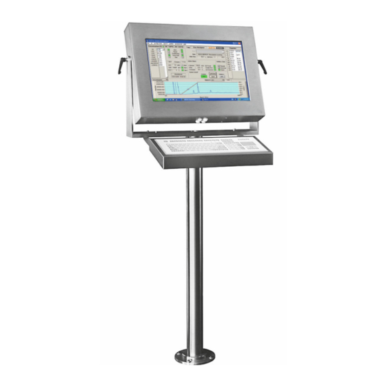
Product Description Definition The POLARIS Remote KVM Analog device from BARTEC is a display, optionally with keyboard, mouse and touch screen which can operate a server or PC in the safe era in hazardous areas Zones 21 and Zone 2 and Zone 22. -
Page 13: Schematic Design
POLARIS Remote Technical Data POLARIS II Remote KVM Analog Schematic design Illustration 3: Simple system structure Explosion protection and approvals Explosion protection POLARIS II Typ 17-72V5-**** ATEX II 3G Ex nA ic IIC T5 Gc Ex protection II3(2)G (1)G Ex nA ic [ic] [ib Gb) [op is Ga] IIC T4/5 Gc (maximum marking) II 2D Ex ib tb IIIC T100°C Db -20 °C ≤... -
Page 14: Technical Data
POLARIS Remote Technical Data POLARIS Remote KVM Analog Technical Data General data Construction Stainless steel enclosure Connection to the PC Direct connection to VGA USB for Keyboard & Mouse (Local Unit) RS 232 for Touchscreen Extension by means of an STP/S 4x2x23 AWG data communication cable Conductor length up to 200 m with resolution 1680 x 1050... -
Page 15: Characteristics Polaris Remote Zero Client Pc 19,1
POLARIS Remote Technical Data POLARIS II Remote KVM Analog 4.1.1 Characteristics POLARIS Remote PC 19,1" Display 19.1" graphics-capable TFT display SXGA resolution 1.280 x 1.024 pixels 16.7 million colours Brightness 300 cd/m Visible surface approx. 376 x 301 mm Contrast1300:1 Backlight LED technology, Service life approx... -
Page 16: Kenndaten Tastatur Varianten
POLARIS Remote Technical Data POLARIS Remote KVM Analog 4.1.3 Kenndaten Tastatur Varianten Keyboard with integrated Touchpad Variants Keyboard with Trackball 38 mm Keyboard with Trackball 50 mm Material (conditionally UV-resistant) Polyester foil of Aluminium plate mounted in stainless steel enclosure Protection class IP65 (statisch) ca. -
Page 17: Heating (Optional) For Version Up To -20°C
POLARIS Remote Technical Data POLARIS II Remote KVM Analog 4.1.4 Heating (Optional) for Version up to -20°C Type HCS 40 Ex protection type II 2G Ex db IIC T4 II 2D td IIIC T135°C Product marking Certification PTB 03 ATEX 1139 X Material Black aluminium Power... -
Page 18: Product Labelling
POLARIS Remote Technical Data POLARIS Remote KVM Analog Product Labelling Type label example Technical data subject to change without notice. 12/37 07/2018... -
Page 19: Transport And Assembly
A written report of any transport damage or missing items must be given to the appointed forwarder and to BARTEC GmbH immediately on receipt of the delivery. BARTEC GmbH’s warranty conditions do not cover damage caused by incorrect storage. Required Tools:... -
Page 20: Installation
POLARIS Remote Technical Data POLARIS Remote KVM Analog Installation We recommend setting up the complete system under laboratory conditions and testing it before it is permanently installed. If a long connection cable is not available, please use a patch cable to test the basic functions. DANGER Electrostatic charging through a stream of particles. -
Page 21: Mechanical Installation
POLARIS Remote Technical Data POLARIS II Remote KVM Analog Mechanical installation CAUTION This device is heavy (approx .17 kg). Risk of injury if lifted or moved incorrectly. Movable enclosure parts on the swivel-mounted enclosure. There is a risk of injury by hands being crushed. 3 people are required to set up the POLARIS. -
Page 22: Floor Mounting
POLARIS Remote Technical Data POLARIS Remote KVM Analog 6.2.1 Floor mounting Illustration 4: Drilling pattern - supporting system for floor mounting 6.2.2 Wall mounting Illustration 5: Drilling pattern - supporting system for wall mounting Technical data subject to change without notice. 16/37 07/2018... -
Page 23: Rotating/ Inclining
POLARIS Remote Technical Data POLARIS II Remote KVM Analog 6.2.3 Table mounting Illustration 6: Drilling pattern - supporting system for table mounting 6.2.4 Rotating/ Inclining Rotating The POLARIS is fixed using two side T screws. The angle of rotation can be changed once the screws have been loosened Inclining The POLARIS is fixed on the carrier system using two hexagon socket screws M10 and a T screw. -
Page 24: Electrical Installation
POLARIS Remote Technical Data POLARIS Remote KVM Analog Electrical Installation 6.3.1 Installation guidelines Only qualified personnel, i.e. trained electricians will have the required specialised knowledge to be able to do all the electrical work. Familiarity with and the technically perfect implementation of the safety instructions described in this manual are preconditions for safe installation and commissioning. -
Page 25: Pe Conductor Connection
POLARIS Remote Technical Data POLARIS II Remote KVM Analog 6.3.2 PE conductor connection DANGER Death or danger of injury as a result of no PE conductor connection. There is no explosion protection. Equipotential bonding with a core cross-section of at least 4 mm is to be set up for the POLARIS (see Figure). -
Page 26: Junction Box
POLARIS Remote Technical Data POLARIS Remote KVM Analog Junction Box DANGER Non-certified cable glands and non-sealed cable entries endanger the IP protection and accordingly the protection against explosions. There is a risk of fatal injury in an explosive atmosphere! Use Ex-certified cable glands. Close non-sealed cable entries. -
Page 27: Polaris Junction Box
POLARIS Remote Technical Data POLARIS II Remote KVM Analog 6.4.1 POLARIS Junction Box Illustration 9: POLARIS II junction box 6.4.2 Terminal assignment X1 Interface AC/DC Signal Description X1-1 Supply Internal protective, protective earth X1-2 Supply L1/+ AC 230 V ± 10 %/ DC 24 V ± 10 % X1-3 Supply Neutral conductor... -
Page 28: Terminal Assignment X1 With Heating Hcs (Optional)
POLARIS Remote Technical Data POLARIS Remote KVM Analog 6.4.3 Terminal assignment X1 with Heating HCS (optional) Terminal Interface AC/DC Signal Description X1-1 Supply Internal protective, protective earth X1-2 Supply L1/+ AC 230 V ± 10 % or DC 24 V ± 10 % X1-3 Supply Neutral conductor... -
Page 29: Terminal Assignment X2
POLARIS Remote Technical Data POLARIS II Remote KVM Analog 6.4.4 Local Unit Illustration 12: Terminal assignment X2 More information please see user manual from the KVM. 6.4.5 Properties of local unit Keyboard and mouse emulation for Plug & Play functionality. The PC boots under all conceivable circumstances. -
Page 30: Establishing The Lan Connection
POLARIS Remote Technical Data POLARIS Remote KVM Analog 6.4.9 Establishing CAT cable Two RJ45 connectors for customer assembly are enclosed for the connection. Illustration 13: RJ 45-plug For an Ethernet connection, observe the instructions in Chapter 4.5 "EMC". Assembly The plug connector can be used for cables with an external diameter of 4.5...8.0 mm (suitable for LAN STP cables, CAT.7 4x2x23 AWG;... - Page 31 POLARIS Remote Technical Data POLARIS II Remote KVM Analog Use a small diagonal cutter to cut the core wires (see illustration). Establish core contact by pressing the terminal (10) blocks together (see fig.) It is also possible to use standard pliers as an aid.
-
Page 32: Emc (Electromagnetic Compatibility)
POLARIS Remote Technical Data POLARIS Remote KVM Analog EMC (Electromagnetic Compatibility) 6.5.1 Note This is a class A unit and can cause radio interference in residential areas; if it does, the owner/managing operator may be required to implement suitable measures and pay for loss or damage. -
Page 33: Back-Up Fuse
PE/PA. 6.5.3 Back-up fuse We recommend protecting the POLARIS with an upstream fuse to prevent blowing the fuse inside the device. Only BARTEC can change the internal fuse. Upstream fuse for AC: 5 AT DC: 5 AT 6.5.4... -
Page 34: Examples Of Shielding Connections
POLARIS Remote Technical Data POLARIS Remote KVM Analog The plug casing of some controllers is not always well connected to earth. In such cases it may prove advantageous to insulate the shielding from the sub-D plug of the controller and connect it directly to the protective earth conductor by means of a cable that should be kept as short as possible (0.75 mm²... -
Page 35: Commissioning
POLARIS Remote Technical Data POLARIS II Remote KVM Analog Commissioning For electrical systems the relevant installation and operating specifications (e.g. Directives 99/92/EC and 94/9/EC, BetrSichV and the applicable national ordinances, IEC 60 079-14 and the DIN VDE 0100 series) must be observed. The operator of an electrical system in a hazardous environment must keep the operating equipment in an orderly condition, operate it correctly, monitor it and do the required maintenance and repairs. -
Page 36: Operation
POLARIS Remote Operation POLARIS II Remote KVM Analog Operation Once the final inspection has been carried out, the device can be put into operation. The POLARIS series does not have any ON/OFF switch. An external power switch is used to turn the device on and off. Technical data subject to change without notice. -
Page 37: Touch Screen
POLARIS Remote Troubleshooting POLARIS II Remote KVM Analog Troubleshooting Fault Possible Cause Remedy Check wire ring No display No signal to the local unit Backlighting is defective. Return to manufacturer Device is defective Return to manufacturer Check diameter and length of the Power supply is too low conductor. -
Page 38: Maintenance, Inspection, Repair
POLARIS Remote Maintenance, Inspection POLARIS II Remote KVM Analog Repair Maintenance, Inspection, Repair Only trained and qualified personnel may commission and do maintenance work on the POLARIS! Trained qualified personnel are people who are familiar with the installation, assembly, commissioning and operation of the POLARIS, have been instructed about the risks and have the appropriate qualifications by virtue of the work they do. -
Page 39: 10.3.1 Instructions For Repairs
If you wish to send in a defective device for repair, please read the RMA procedure guidance first. Then fill in and sign the RMA (Return Merchandise Authorisation) form and send it to our "Retouren Center". E-mail: services@bartec.de Fax: +49 7931 597-119 We cannot guarantee any contractually agreed processing times for devices that are sent in without an RMA number. -
Page 40: Accessories, Spare Parts
Repair, Disposal, POLARIS Remote Dispatch, Packaging POLARIS II Remote KVM Analog Accessories, Spare Parts Keyboard including stainless steel enclosure Keyboard with integrated trackball 38 mm Keyboard with integrated trackball 50 mm Keyboard with integrated touchpad Stand for floor mounting Material: Stainless steel DIN 1.4301 ... -
Page 41: Order Numbers
POLARIS Remote Order Numbers POLARIS II Remote KVM Analog Order Numbers Order Number: 17-72V4-ABZ0/CD00 Change the ABCD code with the right Number Technical data subject to change without notice. 35/37 04/2012... -
Page 42: Additional Information
POLARIS Remote Additional Information POLARIS II Remote KVM Analog Additional Information Technical data subject to change without notice. 36/37 04/2012... -
Page 43: Eu Konformitätserklärung
EU Konformitätserklärung...
Need help?
Do you have a question about the 17-72V5 Series and is the answer not in the manual?
Questions and answers