Table of Contents

Related Manuals for GMI D6037S


Summary of Contents for GMI D6037S
- Page 1 D6037S - D6037D INSTRUCTION MANUAL SIL 2 Switch/Proximity Detector Repeater Transistor Out, DIN-Rail and Termination Board, Models D6037S, D6037D D6037 - SIL 2 Switch/Proximity Detector Repeater Transistor Out G.M. International ISM0409-0...
- Page 2 Characteristics General Description: The single and dual channel Switch/Proximity Detector Repeater, D6037S and D6037D module is a unit suitable for applications requiring SIL 2 level (according to IEC 61508:2010 Ed. 2) in safety related systems for high risk industries. The unit can be configured for switch or proximity detector (EN60947-5-6, NAMUR), NO or NC and for NO or NC optocoupled open collector transistor output.
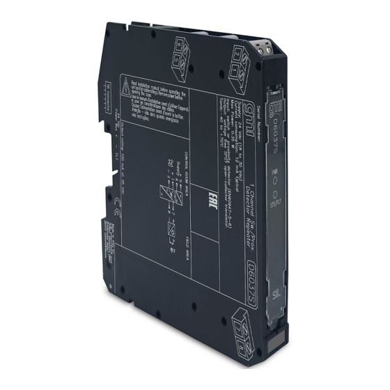
- Page 3 Front Panel and Features SIL 2 according to IEC 61508:2010 Ed. 2 for Tproof = 8 / 20 years (≤10% / >10 % of total SIF) for D6037S and D6037D. PFDavg (1 year) 1.21 E-04, SFF 77.15 % for D6037S.
- Page 4 Resistors R1 - R2 used with Termination voltage free contact required Power and board for line fault detection. Fault Bus connector MODEL D5037S MODEL D6037S Supply 24 Vdc voltage free voltage free Proximity Contact Contact Out (SIL 2) Resistors R1 - R2 used with...
- Page 5 On the section “Function Diagram” and enclosure side a block diagram identifies all connections. Identify the number of channels of the specific card (e.g. D6037S is a single channel model and D6037D is a dual channel model), the function and location of each connection terminal using the wiring diagram on the corresponding section, as an example: Connect 24 Vdc power supply positive at terminal “5”...
- Page 6 Configuration D6037D A configuration DIP switch is located on component side of pcb. This switch allows the configuration of input/output relationship, fault detection functions and operating mode. Dip switch factory settings. All Switches are OFF Dip switch configuration Line fault Disabled Setting detection...
- Page 7 Output Input Output NO-NO or NC-NC For SIL Application Configuration DIP Switch factory settings (valid for D6037S and D6037D) SW1 SW2 SW3 SW4 Note: SW3 and SW4 used only in D6037D. D6037D Configuration Summary Table Channel Channel Line fault detection...
Need help?
Do you have a question about the D6037S and is the answer not in the manual?
Questions and answers