
Subscribe to Our Youtube Channel
Related Manuals for GMI D5030S


Summary of Contents for GMI D5030S
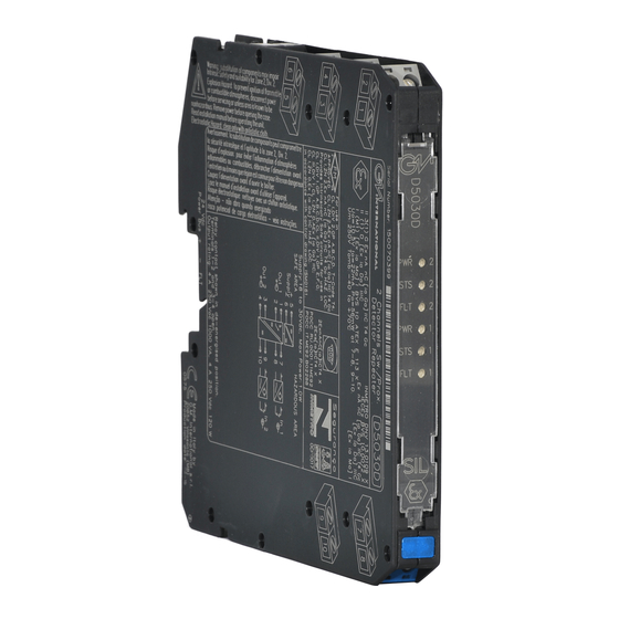
- Page 1 D5030S - D5030D INSTRUCTION MANUAL SIL 3 Switch/Proximity Detector Repeater Relay Output, DIN Rail, Models D5030S, D5030D D5030 - SIL 3 Switch/Proximity Detector Repeater Relay Output G.M. International ISM0106-11...
-
Page 2: Technical Data
(according to IEC 61508:2010 Ed. 2) in safety related systems for high risk industries. The unit can be configured for switch or proximity detector (EN60947-5-6, NAMUR), NO or NC and for NE or ND SPST (D5030D) or SPDT (D5030S) relay output contact. -
Page 3: Ordering Information
Ordering Information Power Bus and DIN-Rail accessories: Model: D5030 Connector JDFT049 Cover and fix MCHP196 1 channel Terminal block male MOR017 Terminal block female MOR022 2 channels Front Panel and Features SIL 3 according to IEC 61508:2010 Ed. 2 for Tproof = 2 / 10 years (≤10% / >10 % of total SIF), considering 100 mA max contact current. PFDavg (1 year) 4.92 E-05, SFF 90.06 %, with independent channel configuration. - Page 4 Parameters Table In the system safety analysis, always check the Hazardous Area/Hazardous Locations devices to conform with the related system documentation, if the device is Intrinsically Safe check its suitability for the Hazardous Area/Hazardous Locations and group encountered and that its maximum allowable voltage, current, power (Ui/Vmax, Ii/Imax, Pi/Pi) are not exceeded by the safety parameters (Uo/Voc, Io/Isc, Po/Po) of the D5030 series Associated Apparatus connected to it.
- Page 5 Relay contact shown in de-energized position. voltage free contact required Power and Terminals 1-2 and 3-4 open. Fault Bus for line fault detection. Internal Dip switches programmable MODEL D5030S Supply 24 Vdc voltage free voltage free Proximity Contact Contact Out NO Contact (SIL 3)
-
Page 6: Operation
Connect SPDT (D5030S) or SPST (D5030D) relay contacts checking the load rating to be within the contact maximum rating (4 A 250 Vac 1000 VA, 4 A 250 Vdc 120 W resistive load, limit current to 100 mA maximum for SIL 3 applications). -
Page 7: Dip Switch Configuration
Configuration D5030D used as double channel A configuration DIP switch is located on component side of pcb. This switch allows the configuration of input/output relationship, fault detection functions and operating mode. WARNING: dip-switch 6-7-8 must be set to “OFF” position. Dip switch factory settings. - Page 8 Configuration D5030D used as duplicator or fault output A configuration DIP switch is located on component side of pcb. This switch allows the configuration of input/output relationship, fault detection functions and operating mode. WARNING: Terminals 9-10 must be shorted to set module as Duplicator or Fault Out. Dip-switch 3 must be set to “OFF”...
- Page 9 Configuration D5030S A configuration DIP switch is located on component side of pcb. This switch allows the configuration of input/output relationship, fault detection functions and operating mode. WARNING: Dip-switch 7-8 must be set to “OFF” position. Dip switch factory settings. All Switches are OFF Dip switch configuration 7-8 must be set to "OFF"...
- Page 10 Configuration DIP Switch factory settings (valid for D5030S and D5030D) SW1 SW2 SW7 SW8 D5030D (used as double channel) Configuration Summary Table WARNING: dip-switch 6-7-8 must be set to “OFF” position. Channel Channel Line fault detection IN/OUT Operation Disabled NO-NE or NC-ND...
Need help?
Do you have a question about the D5030S and is the answer not in the manual?
Questions and answers