Table of Contents
Advertisement
Quick Links
Advertisement
Table of Contents

Related Manuals for Global Specialties 1410


Summary of Contents for Global Specialties 1410
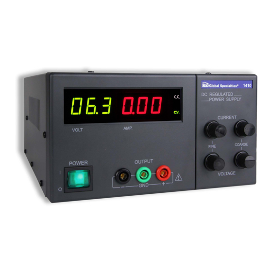
- Page 1 1410 90W DC User Power Supply Manual 1.800.561.8187 information@itm.com www. .com...
-
Page 2: Safety Summary
Safety Summary The following safety precautions apply to both operating and maintenance personnel and must be observed during all phases of operation, service, and repair of this instrument. Before applying power, follow the installation instructions and become familiar with the operating instructions for this instrument. GROUND THE INSTRUMENT To minimize shock hazard, the instrument chassis and cabinet must be connected to an electrical ground. - Page 3 Specialties (Cal Test Electronics) for service and repair to ensure that safety features are maintained. WARNINGS AND CAUTIONS WARNING and CAUTION statements, such as the following examples, denote a hazard and appear throughout this manual. Follow all instructions contained in these statements. A WARNING statement calls attention to an operating procedure, practice, or condition, which, if not followed correctly, could result in injury or death to personnel.
-
Page 4: Compliance Statements
1 INTRODUCTION The 1410 Power Supply is a high quality serial control type DC voltage or constant current mode whose output can be varied from 0 to 30 volts. This compact unit has separate 3-digit LED voltage and current meters for monitoring of the output voltage and current simultaneously. -
Page 5: Specifications
The limiting current values can be preset in the full range of the rated values. Multiple units of the 1410 can be connected in series to provide higher output voltage. Multiple of the 1410 can be connected in parallel (Master/ Slave configuration) to achieve higher output current. - Page 6 OUTPUT Output terminals ( color ) ±180 V INSTRUMENTATION Voltmeter 3 digits Ammeter 3 digits FUNCTIONS Can be connected in Serial connection series (within limits of ( independent control mode ) ground proof voltage) Can be operated in Parallel operation “one-control”...
-
Page 7: Precautions For Use
version from our website. 4 PRECAUTIONS FOR USE voltage can be found on the rating label under the unit. Before plugging into the AC supply outlet, check if the input rating conforms with your local supply. A voltage selector is on the back of the unit. Switch the voltage selector to the correct position before use. - Page 8 5 EXPLANATION OF PANELS Figure 1 Power Switch DC Voltmeter DC Ammeter Constant Current Mode (C.C.) Indicator Constant Voltage Mode (C.V.) Indicator Voltage Coarse Adjust Voltage Fine Adjust Current Coarse Adjust Current Fine Adjust 10. Output Terminal Positive (+) 11. Output Terminal Negative (–) 12.
-
Page 9: Operation Procedures
When using the power supply in stand-alone mode, simply operate by manipulation of the panel switches and adjustment knobs as needed. position. Two or more units of the 1410 can be connected in series to achieve higher output voltage. The resulting output will be sum of 1.800.561.8187 information@itm.com www. - Page 10 the outputs of the individual units. In this situation; however, care must be taken that the voltage of neither of the terminals, with +180 V. 1.2.1 For connection as shown in Figure 3, the output voltage will be the sum of individual supplies and output current will be limited to within ground terminal to output positive point and for negative ground system, connect the ground terminal to the negative output point.
- Page 11 Two or more units of the 1410 can be connected in parallel to give an increase in output current capacity. The total output current capacity will be the sum of the output currents of the individual units. In this mode of operation, one supply will act as the master and all settings are from the master unit.
-
Page 12: Maintenance
insertion is completed, release the screw driver. See Figure 7. Figure 5 Figure 6 Figure 7 7 MAINTENANCE WARNING To aviod electrical shock, do not perform any servicing other than 1.800.561.8187 information@itm.com www. .com... - Page 13 If the main fuse blows, the power on LED indicator will not light and power supply will not operate. The fuse should not normally open unless a problem has developed in the unit. Try to determine and correct the cause of the blown fuse, then replace only with a fuse of correct rating.
- Page 14 Connect the multimeter to measure the DC voltage across the power supply (+) and (–) output terminals. adjustment knob fully clockwise (maximum output). on the multimeter. Vmax is the maximum normal output of the specific model under calibration. Set the output voltage to about half the maximum allowable output.
-
Page 15: Service And Warranty Information
8 Service and Warranty Information Cal Test Electronics warrants this product to be free from defective material or workmanship for a period of 1 year from the date of original purchase. Under this warranty, Cal Test Electronics is limited to repairing the defective device when returned to the factory, shipping charges prepaid, within the warranty period. - Page 16 20160930 1.800.561.8187 information@itm.com www. .com...
Need help?
Do you have a question about the 1410 and is the answer not in the manual?
Questions and answers