Federal Signal Corporation 350 Installation And Maintenance Instructions Manual
Vibratone electro-mechanical horn
Hide thumbs
Also See for 350:
- Installation instructions manual (20 pages) ,
- Installation instructions manual (16 pages)
Table of Contents
Advertisement
Available languages
Available languages
Quick Links
MODEL 350
Vibratone® Electro-Mechanical Horn
Installation and Maintenance
Instructions
Limited Warranty: This product's limited warranty
can be found at www.fedsig.com/SSG-Warranty.
Messages to Installers and Users
should be installed to code by a licensed electrician
and follow all safety instructions. Failure to do so
may result in property damage, serious injury, or
death.
•
Read and understand instructions before
installing or operating the equipment.
•
SHOCK HAZARD - To avoid electrical shock
hazards, do not connect wires when power is
applied.
•
Optimum sound distribution will be severely
reduced if any objects are in front of the horn.
Ensure that the front of the horn is clear of any
obstructions.
•
All effective warning sounders produce loud
sounds that may cause, in certain situations,
permanent hearing loss. Take appropriate
precautions, such as hearing protection. The
device should be installed far enough away
from potential listeners to limit their exposure
while still maintaining its effectiveness. The
OSHA Code of Federal Regulations 1910.95
Noise Standard provides guidelines that may
be used regarding permissible noise exposure
levels.
•
After installation, test the system to ensure
that it is operating properly.
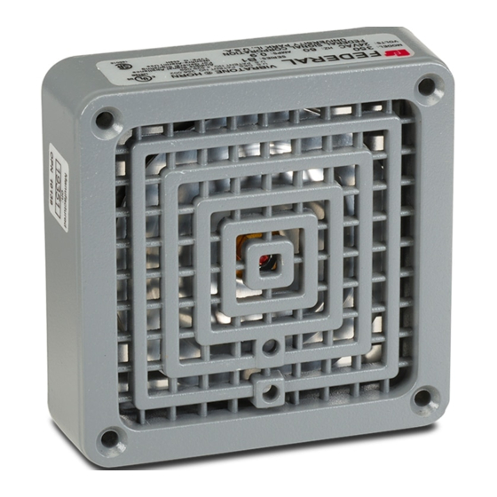
Overview: The Model 350 horn is a very loud
electro-mechanical device that produces a horn
tone by vibration of a diaphragm. This horn is
capable or reproducing coded blasts or sustained
tone. The horn has a duty cycle of five minutes on,
five minutes off.
Unpacking the Device: After unpacking the device,
examine it for damage and verify the parts. See
Table 1 for the Carton Contents List. If a part is
This product
missing or appears damaged, do not attempt to
install. Contact Federal Signal Customer Support at
+1 708-587-3587 or iordersup@fedsig.com.
Qty
Mounting the Device
The horn may be directly mounted to a standard
4-inch square electrical box or may be mounted
using various Federal Signal accessories
(purchased separately).
Outlet Box Mounting
To mount the horn to a wall or other flat vertical
surface:
1.
2.
3.
4.
Table 1 Carton Contents List
Description
1
350 Horn
2
8-32 x 1-5/8" oval head screws
2
10-32 x 5/8" oval head tapping screws
1
10-32 x 3/8" hex head tapping screw
1
10-32 x 3/8" hex socket head set screw
Mount a 4-inch square electrical box to the
mounting surface with appropriate user
supplied hardware.
Connect the wires per the Electrical
Connections section below.
Mount the horn to the box using the two 8-32
by 1-5/8-inch screws provided.
Install the two 10-32 by 5/8-inch tapping
screws into the two unused screw openings
on the horn. See Figure 1.
Advertisement
Table of Contents

Related Manuals for Federal Signal Corporation 350


Summary of Contents for Federal Signal Corporation 350
- Page 1 Connect the wires per the Electrical that it is operating properly. Connections section below. Overview: The Model 350 horn is a very loud Mount the horn to the box using the two 8-32 electro-mechanical device that produces a horn by 1-5/8-inch screws provided.
-
Page 2: Semi-Flush Mounting
Figure 1 Outlet Box Mounting Mount the Model Flush Wall Mount Box wall box into the wall with the box edge flush with the finished wall. Connect the wires per the Electrical Connections section below. Mount the horn and Flush Mount Grille accessory to the Flush Wall Mount Box wall box using the two 8-32 by 1-5/8-inch screws provided. - Page 3 Figure 4 Weatherproof Box Mounting Attach the horn to the panel using the four 8-32 by 1-5/8-inch screws, gasket, and four 8-32 locknuts provided with Panel Mount Gasket Kit K8435666A. Connect wires per Electrical Connections section below. See Figure 6. Figure 6 Recessed Weatherproof Panel Mounting 290A2450-03C Weatherproof Panel Mounting...
-
Page 4: Electrical Connections
Optional Volume Control Description Model/Part Number Semi-Flush Mounting Plate The 350 horn is shipped with the volume set for maximum sound output. However, you can reduce Flush Wall Mount Box the sound level with the provided 10-32 hex socket Flush Mount Grille head set screw. -
Page 5: Montaje Del Dispositivo
Conecte los cables según la sección Conexiones asegurarse de que funcione correctamente. eléctricas a continuación. Descripción: La bocina Model 350 es un dispositivo Monte la bocina en la caja usando los dos electromecánico muy fuerte que produce un tono de tornillos 8-32 por 1-5/8 pulgadas provistos. -
Page 6: Montaje Empotrado
Figura 1 Montaje de la caja de salida Montaje empotrado El montaje empotrado en la pared requiere el uso de la caja de montaje empotrado en la pared modelo FB de Federal Signal y los accesorios de rejilla de montaje empotrado FG. - Page 7 Figura 4 Montaje de caja impermeable Fije la bocina al panel con los cuatro tornillos 8-32 por 1-5/8 pulgadas, la junta y las cuatro contratuercas 8-32 provistas con el juego de juntas de montaje en panel K8435666A. Conecte los cables según la sección Conexiones eléctricas a continuación.
-
Page 8: Conexiones Eléctricas
Modelo/Número de Control de volumen opcional pieza Placa de montaje La bocina 350 se envía con el volumen configurado para semiempotrado la salida máxima de sonido. Sin embargo, puede reducir el nivel de sonido con el tornillo de fijación de cabeza Caja empotrada para montaje hexagonal 10-32 provisto. -
Page 9: Montage De L'appareil
Connexions électriques ci-dessous. assurer qu’il fonctionne correctement. Fixez l’avertisseur au boîtier à l’aide des deux vis Présentation : L’avertisseur modèle 350 est un 8-32 de 1-5/8 pouce fournies. appareil électromécanique très puissant qui produit un Installez les deux vis autotaraudeuses 10-32 de avertissement sonore par la vibration d’un diaphragme. -
Page 10: Montage Encastré
Figure 1 Montage du boîtier de prise Montez le boîtier de montage mural de modèle encastrable dans le mur avec le bord du boîtier encastré au mur fini. Branchez les fils conformément à la section Connexions électriques ci-dessous. Montez l’avertisseur et l’accessoire de la grille de montage encastré... - Page 11 Figure 4 Montage d’un boîtier résistant aux intempéries Faites une découpe dans le panneau en suivant le modèle fourni avec le kit de joint de montage du panneau K8435666A. Fixez l’avertisseur au panneau à l’aide des quatre vis 8-32 de 1-5/8 pouce, du joint et des quatre contre-écrous 8-32 fournis avec le kit de joint de montage du panneau K8435666A.
-
Page 12: Commande D'accessoires
Connexions électriques Tests/fonctionnement Le modèle 350 est fourni avec deux fils pour les Après l’installation, testez le système pour vérifier que raccordements électriques. Pour effectuer les chaque signal fonctionne. Établissez un programme de raccordements : tests périodiques de l’appareil. Fournissez une copie de ces instructions à...
Need help?
Do you have a question about the 350 and is the answer not in the manual?
Questions and answers