Table of Contents
Advertisement
Quick Links
Advertisement
Table of Contents

Related Manuals for Flomotion Systems V21


Summary of Contents for Flomotion Systems V21
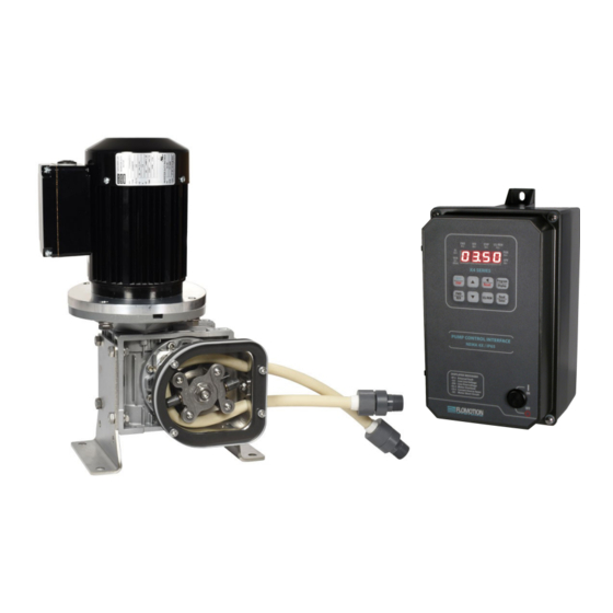
- Page 1 Installation and Operation Manual Peristaltic Chemical Feed Pump October 2021 Flomotion Systems, Inc. 3 N. Main St, Middleport, NY 14105 Toll Free: (800)909-3569 (U.S. & Canada) Tel: (716)691-3941 Fax: (716)691-1253 info@flomotionsystems.com www.flomotionsystems.com...
-
Page 2: Table Of Contents
1.3 C ...................................3 USTOMER ODIFICATION 1.4 I ..............................3 NFORMATION FOR ETURNING UMPS 1.5 W ......................................4 ARRANTY 2.0 – V21 Series Pump and Pumphead..........................5 2.1 T ............................6 UBING PINDLE AND OVER NSTALLATION 2.2 M .........................7 OUNTING UMP ON EARBOX NSTALLATION OF OLLET 2.3 P... -
Page 3: System Overview
1.4 Information for Returning Pumps Equipment that has been contaminated with, or exposed to, body fluids, toxic chemicals or any other substance hazardous to health must be decontaminated before it is returned to Flomotion Systems or its distributor. Please contact Flomotion Systems for a Return Authorization number and instructions for returning the pump. -
Page 4: Warranty
Flomotion Systems, Inc. agrees that, at its option, it will repair or replace the defective product. Any product repaired or replaced under this warranty will be warranted only for the remainder of the original product warranty period. -
Page 5: V21 Series Pump And Pumphead
ROLLER ASSEMBLY COLLET SCREW 4MM HEX WRENCH 7 NT.M 60 IN.OZ IMPORTANT: The V21 Series is equipped with a pump cover for safety and protection against chemical spills. The cover must be installed whenever the pump is in use. pg. 5... -
Page 6: Tubing, Spindle And Cover Installation
2.1 Tubing, Spindle and Cover Installation ! IMPORTANT: Disconnect pump controller from power supply BEFORE changing tubing! Item No. Part No. Description PHSS-R Pump Housing, Rear RA-01 Roller Assembly PHC01 Cover 100324 Collet Screw PHG01 Cover Gasket 100307C Cover Screw Tube Varies with tubing selection* Tube Seal... -
Page 7: Mounting Pump On Gearbox, Installation Of Collet
2.2 Mounting Pump on Gearbox, Installation of Collet Item No. Part No. Description PHSS-R Pump Housing with Tube Seal 100306 Collet 100330 Pump Mounting Screws Tubing pg. 7... -
Page 8: Pump Mounting And Collet Installation Procedure
2.3 Pump Mounting and Collet Installation Procedure 1. To install the pump housing on the gearbox, slide it over the central pilot on the gearbox adapter plate. Next install and torque the mounting screws to 5 NT.M (45 in. oz). 2. -
Page 9: Tube And Roller Installation
2.4 Tube and Roller Installation ! IMPORTANT: Disconnect pump controller from power supply BEFORE changing tubing! ! IMPORTANT Make sure pump suction and discharge lines are completely drained and isolated. Note that the tubing hose seal size must match the selected tubing size. Disassembly 1. - Page 10 4. Remove the roller assembly. 5. Remove worn pump tubing from pumphead. 6. Remove and inspect collet for wear. Note that the collet may remain in the roller assembly when the roller assembly is removed from the pump shaft. pg. 10...
- Page 11 7. Clean inside of pump housing with damp rag or an appropriate cleaning solution to remove any chemical or tubing residue. Reassembly 1. Reinstall the collet onto the pump shaft. IMPORTANT: There is a slot in the collet that the flat drive tang on the gearbox shaft must slide into.
- Page 12 3. Install tubing into the pumphead. Note: during tubing installation the loop of tubing may develop a twist. Examine the tubing for this condition and if needed turn one end of the tubing where it exits the tubing clamp to eliminate the twist.
- Page 13 5. Align marks on tubing with outside edge of the tubing Clamp. Mark an 11 inch length of tubing and locate the marks at the outside edge of the tubing seal (see arrows) Tubing seal size varies with the selected tubing size. See tables on following pages for details...
- Page 14 7. Inspect pump cover gasket. Replace if damaged. Reinstall pump cover gasket and cover. Align the tubing marks with the outside edge of the Hose Seal. pg. 14...
-
Page 15: Tubing & Connections
2.5 Tubing & Connections Tubing connectors are available for many configurations. See the drawing below for details. V21 SERIES ESTIMATED PUMPING CAPACITY* *Actual flow rates may vary Tubing Size 1.6mm bore 3.2mm bore 4.8mm bore 6.4mm bore 8mm bore 9.6mm bore (1/16”) -
Page 16: V21 Series Gearbox
3.0 – V21 Series Gearbox 3.1 Run-in Period The maximum efficiency of worm reducers is obtained after a “Run-In” period. The length of time required will depend on the load applied and may be two to four hours at rated load and will be considerably longer at lighter loads. -
Page 17: K4 Pump Controller
IMPORTANT: Make sure the Mains voltage jumper is in the correct location for the supplied voltage. See the K4 drive operating instructions booklet for details. Shown here are program settings specific to the operation with the V21 Peristaltic Pump. 4.2 Programming K4 Default Program Settings 0.04 = 0000 GFCI disabled, enable if power pump through GFCI mains circuit (some additional noise from the drive is... -
Page 18: Making Programming Changes
4.3 Making Programming Changes 1. Press the Stop key to make sure the pump is stopped. Display will read Stop. 2. Press the Program key. 3. Using the arrow keys, enter the parameter number you would like to change and then press Enter. 4. - Page 19 4.7 Controller Wiring Examples pg. 19...
-
Page 20: Tubing Rupture Detector
5.0 - Tubing Rupture Detector Rupture Detector System Overview 5.1 Alarm Causes A rupture alarm is triggered by the presence of a conductive fluid in the pump. When the fluid bridges the two stainless steel electrodes in the LIQUID SENSOR in the pump the alarm is triggered. 5.2 What to do in an alarm condition To clear the alarm, first stop the pump and disconnect power from the pump controller. -
Page 21: Troubleshooting Guide
6.0 Troubleshooting Guide Pump does not power up. No Power to the pump. Verify the pump is plugged into a powered receptacle and the electrical circuit breaker is in the “ON” position. Verify the motor and drive power connections for proper wiring. Pump/Roller Assembly does not rotate. -
Page 22: Recommended Spare Parts
7.0 Recommended Spare Parts Select correct size from Page 15. • Pump Tubing. • Hose Barb and Collar (2 per pump). • Tube Seal • Roller Assembly Spare Parts Kit. #RK-01. pg. 22...
Need help?
Do you have a question about the V21 and is the answer not in the manual?
Questions and answers