Flomotion Systems 2001H Series Installation And Operation Manual
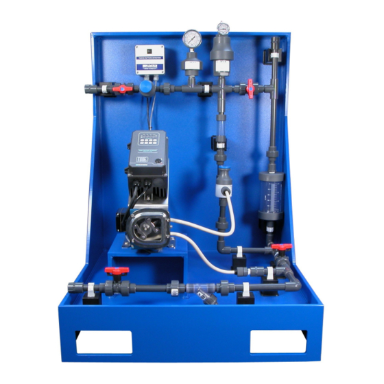
Peristaltic chemical feed pump
Hide thumbs
Also See for 2001H Series:
- Installation and operation manual (22 pages) ,
- Installation and operation manual (27 pages)
Table of Contents
Advertisement
Quick Links
Advertisement
Table of Contents

Related Manuals for Flomotion Systems 2001H Series


Summary of Contents for Flomotion Systems 2001H Series
- Page 1 2001H Series Peristaltic Chemical Feed Pump...
- Page 3 Installation and Operation Manual 2001H Series Peristaltic Chemical Feed Pump December 2019 Flomotion Systems, Inc. 3 N. Main St, Middleport, NY 14105 Toll Free: (800)909-3569 (U.S. & Canada) Tel: (716)691-3941 Fax: (716)691-1253 info@flomotionsystems.com www.flomotionsystems.com...
-
Page 5: Table Of Contents
1.3 R ......................................5 ECEIVING 1.4 C ...................................5 USTOMER ODIFICATION 1.5 I ..............................5 NFORMATION FOR ETURNING UMPS 2.0 – 2001H SERIES PUMP AND PUMPHEAD............................6 2.1 T ............................7 UBING PINDLE AND OVER NSTALLATION 2.2 M ........................8 OUNTING UMP ON EARBOX NSTALLATION OF OLLET 2.3 P... -
Page 6: System Overview
1.2 Warranty Flomotion Systems, Inc. warrants the 2001 Series pumps to be free of defects in material and workmanship for a period of eighteen months from the date of sale to the user, or two years from the date of shipment, which ever occurs first. -
Page 7: Customer Modification
1.5 Information for Returning Pumps Equipment that has been contaminated with, or exposed to, body fluids, toxic chemicals or any other substance hazardous to health must be decontaminated before it is returned to Flomotion Systems or its distributor. Please contact Flomotion Systems for a Return Authorization number and instructions for returning... -
Page 8: 2001H Series Pump And Pumphead
2.0 – 2001H Series Pump and Pumphead The 2001H Series pumphead has two spring-loaded working rollers, which automatically compensate for minor variations in tubing wall thickness, giving extended tube life. ROLLER ASSEMBLY COLLET SCREW 5MM HEX WRENCH 7 NT.M 60 IN.OZ IMPORTANT: The 2001 Series is equipped with a pump cover for safety and protection against chemical spills. - Page 9 2.1 Tubing, Roller Assembly and Cover Installation ! IMPORTANT: Disconnect pump controller from power supply BEFORE changing tubing! Item No. Part No. Description Pump Body RA-01 Roller Assembly 100304B Cover 100324 Collet Screw 100305C Cover Gasket 100307C Cover Screw varies Tubing Varies with tubing selection* Tube Seal...
-
Page 10: Mounting Pump On Gearbox, Installation Of Collet
2.2 Mounting Pump on Gearbox, Installation of Collet Item No. Part No. Description Pump Housing with Tube Seal & Tube Seal Cover 100306 Collet 100312 Pump Mounting Screws Tubing... -
Page 11: Tube And Roller Installation
2.3 Tube and Roller Installation ! IMPORTANT: Disconnect pump controller from power supply BEFORE changing tubing! ! IMPORTANT Make sure pump suction and discharge lines are completely drained and isolated. Note that the tubing hose seal size must match the selected tubing size. Disassembly 1. - Page 12 3. Remove 5mm collet screw. 4. Remove the roller assembly. 5. Remove worn pump tubing from pumphead.
- Page 13 6. Remove and inspect collet for wear. Note that the collet may remain in the roller assembly when the roller assembly is removed from the pump shaft. 7. Clean inside of pump housing with damp rag or an appropriate cleaning solution to remove any chemical or tubing residue.
- Page 14 2. Mark an 11” section of tubing, which will be the portion, contained within the pump. Leave sufficient excess on the suction and discharge sides of the pump for the desired connections. If you leave the excess intake tubing in a coil near the pump it will make it easy to feed a new section of tubing through the rollers when the section in the pump becomes worn.
- Page 15 4. Loop tubing around roller assembly between guides as shown. Remove slack in tubing while rotating roller assembly and sliding onto collet. 5. Align marks on tubing with outside edge of the tubing Clamp. Mark an 11 inch length of tubing and locate the marks at the outside edge of...
- Page 16 7. Tighten tubing seal clamp screw. Be sure to tighten firmly to prevent “tubing walk.” Tubing walk can occur when the tubing seal is the wrong size or is not sufficiently tight to keep the rollers from pulling the tubing through the pump as it rotates. Align the tubing marks with the outside edge of the Hose Seal.
-
Page 17: Tubing & Connections
½”NPT Also Available: Color coded Hose B arb Connector for 3/8” & 1/2” O. D. varies with tubing I.D. Polyethylene Tubing 2001H SERIES ESTIMATED PUMPING CAPACITY* *Actual flow rates may vary Tubing No. #119 #120 #25 & 121 #36 & 122 Tubing Size 1.6mm bore... -
Page 18: 2001H Motor & Gearbox
3.0 – 2001H Motor & Gearbox 3.1 Motor Specifications Motor Type: Permanent Split Capacitor or 3-Phase Inverter Duty Rotation: Reversible. Insulation: Class B minimum Finish: Powder-coat gloss black. Thermostat signal wires are not used in the 2001H 3.2 2001H Power &... -
Page 19: Operation And Wiring
4.0 – K4 Pump Controller 4.1 Operation and Wiring For complete details about the motor drive controller please refer to the included K4 SERIES Operating Instructions booklet. Shown here are program settings specific to the operation with the 2001H Peristaltic Pump. 4.2 Programming The programming differs from the factory defaults shown in the SM Vector Operating Instruction booklet only in relation to the following parameters:... - Page 20 4.4 Setting the maximum pumping rate. 1. Fill a calibration cylinder (best to use water, not chemical for testing and calibration) 2. Run the pump at full speed and time the drawdown for 30 sec. (from zero level in cylinder) 3.
- Page 21 4.5 Controller Wiring Examples...
-
Page 22: 2001 Series Tubing Rupture Detector
5.0 - 2001 Series Tubing Rupture Detector Rupture Detector System Overview 5.1 Alarm Causes A rupture alarm is triggered by the presence of a conductive fluid in the pump. When the fluid bridges the two stainless steel electrodes in the LIQUID SENSOR in the pump the alarm is triggered. 5.2 What to do in an alarm condition To clear the alarm, first stop the pump and disconnect power from the pump controller. - Page 23 Notes...
Need help?
Do you have a question about the 2001H Series and is the answer not in the manual?
Questions and answers