Table of Contents
Advertisement
Quick Links
Advertisement
Table of Contents

Related Manuals for Flomotion Systems 4001V Series


Summary of Contents for Flomotion Systems 4001V Series
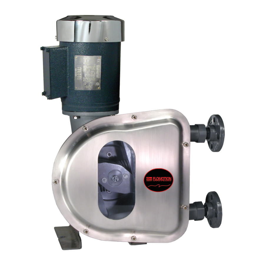
- Page 1 4001V Peristaltic Chemical Feed Pump...
- Page 2 Installation and Operation Manual 4001V Series Peristaltic Chemical Feed Pump January 1, 2018 Flomotion Systems, Inc. 3 N. Main St Middleport, NY 14105 Toll Free: (800)909-3569 (U.S. & Canada) Fax: (716)691-1253 info@flomotionsystems.com www.flomotionsystems.com Flomotion Systems, Inc. 4001V SERIES Pg. 2...
-
Page 3: Table Of Contents
LARM AUSES 5.3.2 What to do in an alarm condition............................. 16 5.3.3 Resetting the alarm.................................. 16 5.3.4 Resuming Service..................................16 5.3.5 Interfacing....................................17 5.3.6 Calibration....................................17 6.0 - PRODUCT USE AND DECONTAMINATION DECLARATION..................18 Flomotion Systems, Inc. 4001V SERIES Pg. 3... -
Page 4: System Overview
1.2 Warranty Flomotion Systems, Inc. warrants the 4001 Series pumps to be free of defects in material and workmanship for a period of eighteen months from the date of sale to the user, or two years from the date of shipment, which ever occurs first. -
Page 5: Receiving
4001V Peristaltic Pump O&M Manual corporation is authorized to assume, for Flomotion Systems, Inc., any other liability in connection with the demonstration or sale of its products. 1.3 Receiving Inspect all cartons for damage, which may have occurred during shipping. Carefully unpack equipment and inspect thoroughly for damage or shortage. -
Page 6: Installation
In addition, your pump may be equipped with an optional Hose Rupture Monitor. Refer to the instructions of this device if required. Flomotion Systems, Inc. 4001V SERIES Pg. 6... -
Page 7: 4001V/Ve Series Pump And Pumphead
IMPORTANT: The 4001 Series is equipped with a pump cover for safety and protection against chemical spills. The cover must be installed whenever the pump is in use. 3.1 Pump Assembly & Tubing Installation ! IMPORTANT: Disconnect pump controller from power supply BEFORE changing tubing! Flomotion Systems, Inc. 4001V SERIES Pg. 7... -
Page 8: Pump Mounting And Collet Installation Procedure
Slide a hose clamp over the the hose clamp over the barbed area. Repeat for end of the hose. the second clamp. Important: Assure that the hose is not twisted when attaching the second clamp. Flomotion Systems, Inc. 4001V SERIES Pg. 8... -
Page 9: Tubing Connections
Estimated Pumping Capacity Tubing I.D. 1/2” 3/4” 1” ml/rev* Pressure rating PSI Max Suction Lift (ft) GPH @ 3-60 RPM* 4.7 - 109 8.1 - 189 14.1 - 329 *Actual flow rates may vary. Flomotion Systems, Inc. 4001V SERIES Pg. 9... -
Page 10: 4001V Motor & Gearbox
4.1 Motor Specifications Motor Type: Permanent Split Capacitor or 3-Phase Inverter Duty Rotation: Reversible. Insulation: Class B minimum Finish: Powder-coat gloss black. (Thermostat wires not used) 4.2 4001VE Motor Wiring Flomotion Systems, Inc. 4001V SERIES Pg. 10... -
Page 11: Operation And Wiring
6.05 = 1010 reset to Flomotion Defaults *8.09 = 0000 to avoid fault when 4-20mA Output is disconnected when not using 4-20mA output Refer to section 4.3 for wiring and program for the above signals and functions. Flomotion Systems, Inc. 4001V SERIES Pg. 11... -
Page 12: 4001V Controller Wiring
4001V Peristaltic Pump O&M Manual 4.3 4001V Controller Wiring Flomotion Systems, Inc. 4001V SERIES Pg. 12... -
Page 13: Gearbox Specifications
Shafts: Stainless steel. Mounting: Face (any angle) or optional footplate. Gearing: AGMA class 9 heat treated steel. 1st stage helical metal, balance spur metal. Bearings: Needle with thrust ball. Flomotion Systems, Inc. 4001V SERIES Pg. 13... -
Page 14: Miscellaneous Diagrams
4001V Peristaltic Pump O&M Manual 5.0 - Miscellaneous Diagrams 5.1 Roller Assembly Flomotion Systems, Inc. 4001V SERIES Pg. 14... -
Page 15: Pump Assembly
4001V Peristaltic Pump O&M Manual 5.2 Pump Assembly Flomotion Systems, Inc. 4001V SERIES Pg. 15... -
Page 16: Tubing Rupture Detector System Overview
Press the pushbutton (LEAK INDICATOR & RESET SWITCH) on the Tubing Rupture Detector to reset the alarm. 5.3.4 Resuming Service Install a fresh tubing insert and the pump is ready to resume service. Flomotion Systems, Inc. 4001V SERIES Pg. 16... -
Page 17: Interfacing
Pump Controller to make that pump take over when the first pump stops. 5.3.6 Calibration Turn the P1 sensitivity adjusting screw counter clockwise several turns. Apply a wet rag to the LIQUID SENSOR electrodes. Adjust the sensitivity clockwise slowly until the alarm trips. Flomotion Systems, Inc. 4001V SERIES Pg. 17... -
Page 18: Product Use And Decontamination Declaration
6.0 - Product use and decontamination declaration Please declare the substances which have been in contact with the product(s) you are returning to Flomotion Systems, Inc. Failure to do so will cause delays in servicing the product. Therefore, please complete this form to ensure that we have the information before receipt of the product(s) being returned. - Page 19 4001V Peristaltic Pump O&M Manual Notes Flomotion Systems, Inc. 4001V SERIES Pg. 19...
Need help?
Do you have a question about the 4001V Series and is the answer not in the manual?
Questions and answers