Flomotion Systems 2001H Series Installation And Operation Manual
Peristaltic chemical feed pump
Hide thumbs
Also See for 2001H Series:
- Installation and operation manual (22 pages) ,
- Installation and operation manual (23 pages)
Table of Contents
Advertisement
Quick Links
Advertisement
Table of Contents

Subscribe to Our Youtube Channel
Related Manuals for Flomotion Systems 2001H Series


Summary of Contents for Flomotion Systems 2001H Series
- Page 1 2001H Series Peristaltic Chemical Feed Pump...
- Page 2 2001H Series Peristaltic Chemical Feed Pump September 2009 Flomotion Systems, Inc. 3 N. Main St Middleport, NY 14105 Toll Free: (800) 909-3569 (U.S. & Canada) Tel: (716) 691-3941 Fax: (716) 691-1253 info@flomotionsystems.com www.flomotionsystems.com Flomotion Systems, Inc. 2001H SERIES Pg. 2...
-
Page 3: Table Of Contents
ONTROLLER HAS BEEN PROGRAMMED FOR ERIES ERIES ETTINGS AS SHOWN ........................................22 BELOW 5.0 - 2001H CONTROLLER WIRING DIAGRAM....................... 24 6.0 - MISCELLANEOUS DIAGRAMS..........................25 6.1 Roller Assembly..................................25 6.2 Hose Seal Installation................................. 26 Flomotion Systems, Inc. 2001H SERIES Pg. 3... -
Page 4: System Overview
1.2 Warranty Flomotion Systems, Inc. warrants the 2001 Series pumps to be free of defects in material and workmanship for a period of eighteen months from the date of sale to the user, or two years from the date of shipment, which ever occurs first. - Page 5 This certificate is required even if the pump is unused. If the pump has been used, the fluids that have been in contact with the pump and the cleaning procedure must be specified along with a statement that the equipment has been decontaminated. Flomotion Systems, Inc. 2001H SERIES Pg. 5...
-
Page 6: 2001 Series Pump And Pumphead
5MM HEX WRENCH 7 NT.M 60 IN.OZ IMPORTANT: The 2001 Series is equipped with a pump cover for safety and protection against chemical spills. The cover must be installed whenever the pump is in use. Flomotion Systems, Inc. 2001H SERIES Pg. 6... -
Page 7: Tubing, Spindle And Cover Installation
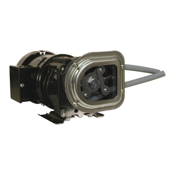
Hose is shown bent forward out of the pump housing to illustrate the correct hose and roller assembly position, prior to sliding the hose and spindle into the housing and over the collet. Flomotion Systems, Inc. 2001H SERIES Pg. 7... -
Page 8: Mounting Pump On Gearbox, Installation Of Collet
2001 Peristaltic Pump O&M Manual 2.2 Mounting Pump on Gearbox, Installation of Collet Pump, Collet & Hose Assy. Item No. Part No. Description 10333 Pump Housing with Hose Seal 100306 Collet 100312 Pump Mounting Screws Hose Flomotion Systems, Inc. 2001H SERIES Pg. 8... -
Page 9: Pump Mounting And Collet Installation Procedure
Orient the collet to allow the drive tang to slide into the slot and push the collet completely onto the gearbox shaft. When the collet bottoms out it is in the correct position. Flomotion Systems, Inc. 2001H SERIES Pg. 9... -
Page 10: Hose And Roller Installation
Note that the hose seal size must match the selected tubing size. Disassembly 1. Remove four (4) 4mm pump cover screws. 2. Loosen Tube Seal Clamp Screw with 5mm hex wrench. 3. Remove 5mm collet screw. Flomotion Systems, Inc. 2001H SERIES Pg. 10... - Page 11 5. Remove worn pump tubing from pumphead. 6. Remove and inspect collet for wear. Note that the collet may remain in the roller assembly when the roller assembly is removed from the pump shaft. Flomotion Systems, Inc. 2001H SERIES Pg. 11...
-
Page 12: Reassembly
Mark an 11.5” section of pump hose. Flomotion Systems, Inc. 2001H SERIES Pg. 12... - Page 13 4. Loop tubing around roller assembly between guides as shown. Remove slack in tubing while rotating roller assembly and sliding onto collet. Flomotion Systems, Inc. 2001H SERIES Pg. 13...
- Page 14 “tubing walk.” Tubing walk can occur when the hose seal is the wrong size or is not sufficiently tight to keep the rollers from pulling the hose through the pump as it rotates. Flomotion Systems, Inc. 2001H SERIES Pg. 14...
- Page 15 Reinstall pump cover gasket and cover. 11.5 inches of hose is the length required inside the pump housing. Hose seal size varies with the selected tubing size. See table on following page for details. Flomotion Systems, Inc. 2001H SERIES Pg. 15...
-
Page 16: Tubing & Connections
(0.06 – 1.5 gph) (1.39 – 37.9 gph) (1.95 – 48.8 gph) 8.8 – 220 rpm gph) ml/rev 0.44 1.88 Color Green White Black Gray Blue Hose Seal PN 100329 100330 100331 100332 100333 100334 Flomotion Systems, Inc. 2001H SERIES Pg. 16... -
Page 17: Tubing And Accessory Part Numbers
100332 Hose Seal 6.4mm (1/4”) bore 100330 Hose Seal 3.2mm (1/8”) bore 100333 Hose Seal 8.0mm (5/16”) bore 100331 Hose Seal 4.8mm (3/16” bore 100334 Hose Seal 9.6mm 3/8”) bore Tubing Connector Adapter Order Guide Flomotion Systems, Inc. 2001H SERIES Pg. 17... -
Page 18: Motor & Gearbox
Shafts: Hardened steel. Mounting: Face (any angle) or optional footplate. Gearing: AGMA class 9 heat treated steel. 1st stage helical metal, balance spur metal. Bearings: Needle with thrust ball. Flomotion Systems, Inc. 2001H SERIES Pg. 18... -
Page 19: 2001H Drive Controller
% Hz HZ MULT 1.00 UNITS DP XXXXX XXX.X LOAD MLT 100 % CONTRAST HIGH SLEEP TH .00 Hz 2.0 Hz SLEEP DL 30.0 SEC 5.0 SEC SLEEP BW TB5 MIN .00 Hz 0%Hz Flomotion Systems, Inc. 2001H SERIES Pg. 19... - Page 20 I GAIN 0.0 SEC D GAIN 0.0 SEC PID ACC 30.0 SEC MIN ALRM 0.0% MAX ALRM 0.0% LANGUAGE ENGLISH FAULT (NA) HISTORY Note 1: See 4.10.3 Description Of Programming Parameters, Step #19. Flomotion Systems, Inc. 2001H SERIES Pg. 20...
-
Page 21: Drive Controller Specifications
IGBT at a very high frequency (known as the carrier frequency) for varying time intervals, the inverter is able to produce a smooth, three phase, sinusoidal output current wave which optimizes motor performance. Flomotion Systems, Inc. 2001H SERIES Pg. 21... -
Page 22: Factory Default / User Settings Record * Controller Has Been Programmed For 2001 Series Series Settings As Shown Below
60.00 Hz 100% Hz AIN FLTR 0.02 SEC 0.02 SEC TB10A OUT NONE @TB10A 60.00 Hz NONE TB10B OUT NONE @TB10B 125 % TB13A NONE 4-20 mA TB13B NONE TB13C NONE TB13D EXT FAULT Flomotion Systems, Inc. 2001H SERIES Pg. 22... - Page 23 I GAIN 0.0 SEC D GAIN 0.0 SEC PID ACC 30.0 SEC MIN ALRM 0.0% MAX ALRM 0.0% LANGUAGE ENGLISH FAULT (NA) HISTORY Note 1: See 4.10.3 Description Of Programming Parameters, Step #19. Flomotion Systems, Inc. 2001H SERIES Pg. 23...
-
Page 24: 2001H Controller Wiring Diagram
2001 Peristaltic Pump O&M Manual 5.0 - 2001H Controller Wiring Diagram Flomotion Systems, Inc. 2001H SERIES Pg. 24... -
Page 25: Miscellaneous Diagrams
2001 Peristaltic Pump O&M Manual 6.0 - Miscellaneous Diagrams 6.1 Roller Assembly Flomotion Systems, Inc. 2001H SERIES Pg. 25... -
Page 26: Hose Seal Installation
2001 Peristaltic Pump O&M Manual 6.2 Hose Seal Installation Flomotion Systems, Inc. 2001H SERIES Pg. 26... - Page 27 2001 Peristaltic Pump O&M Manual Notes Flomotion Systems, Inc. 2001H SERIES Pg. 27...
Need help?
Do you have a question about the 2001H Series and is the answer not in the manual?
Questions and answers