ABB Terra AC Installation Manual
Hide thumbs
Also See for Terra AC:
- Installation manual (76 pages) ,
- User manual (54 pages) ,
- User manual (48 pages)
Table of Contents
Advertisement
Quick Links
Advertisement
Table of Contents

Related Manuals for ABB Terra AC


Summary of Contents for ABB Terra AC
- Page 1 Installation manual Terra AC © Copyright 2020 ABB. All rights reserved Copyright...
- Page 2 All rights to copyrights, registered trademarks, and trademarks reside with their respective owners. ® Copyright ABB EV Infrastructure. All rights reserved. BCM.V3Y01.0-EN | 001...
-
Page 3: Table Of Contents
Contents About this document................7 Function of this document....................7 Target group........................7 Revision history......................... 7 Language..........................7 Illustrations........................7 Units of measurement....................... 7 Typographical conventions....................7 How to use this document....................7 General symbols and signal words..................8 1.10 Special symbols for warnings and dangers................9 1.11 Related documents......................9 1.12... - Page 4 3 Safety 3.1 Liability ............................23 3.2 Required qualifications for the installation engineer ..............23 3.3 Personal protective equipment....................23 3.4 General safety instructions ......................24 3.5 Safety instructions during installation ..................24 3.6 Safety instructions for earthing ............... 错误!未定义书签。 3.7 Signs on the EVSE ........................
- Page 5 Access to parts................... 40 Remove the cabinet cover....................40 Install the cabinet cover....................40 Remove the maintenance cover..................41 Install the maintenance cover...................41 Troubleshooting..................42 10.1 Troubleshooting procedure....................42 10.2 Troubleshooting table.......................42 10.3 De-energize the EVSE....................44 Technical data..................45 11.1 EVSE Type........................45 11.2 Mass ..........................46 11.3 Protective device compliance...................46 11.3.1...
- Page 6 11.13.7 EV charge cable specifications................. 56 11.14 AC output specifications....................56 11.14.1 AC output specifications (Europe)..............56 11.14.2 AC output specifications (North America)............57 11.15 Specific power consumption specifications..............57 11.16 Torque specifications......................57 12 Display Instructions...................58 BCM.V3Y01.0-EN | 001...
-
Page 7: About This Document
About this document Function of this document The document is only applicable for this EVSE (Terra AC), including the variants and 11.1 options listed in section . The EVSE from here on in the document is referred to as the EVSE. -
Page 8: General Symbols And Signal Words
General symbols and signal words Signal word Description Symbol Danger If you do not obey the instruction, this can Refer to section cause injury or death. 1.10 Warning If you do not obey the instruction, this can Refer to section cause injury. -
Page 9: Special Symbols For Warnings And Dangers
Manufacturer and contact data Manufacturer ABB EV Infrastructure George Hintzenweg 81, 3068 AX, Rotterdam, The Netherlands Contact data The local representative of the manufacturer can give you support on the EVSE. You can find the contact data here: https://new.abb.com/ BCM.V3Y01.0-EN | 001... -
Page 10: Abbreviations
1.13 Abbreviations Abbreviation Definition Alternating current Controller area network Central processing unit Direct current Electromagnetic compatibility Electric vehicle EVSE Electric vehicle supply equipment Measuring Instruments Directive Near field communication NoBo Notified body OCPP Open charge point protocol Protective earth Personal protective equipment RFID Radio-frequency identification Note: It is possible that not all abbreviations are present in this document. -
Page 11: Orientation Agreements
Note: It is possible that not all terms are present in this document. 1.15 Orientation agreements Front side: face forward to the EVSE X-direction (positive is to the right) during normal use Y-direction (positive is rearward) Left side Z-direction (positive is upward) Right side Rear side BCM.V3Y01.0-EN | 001... -
Page 12: Description
Description Short description The EVSE (Terra AC) is an AC charging station that you can use to supply electricity to an EV. The Terra AC offers tailor-made, intelligent and network charging solutions for your company or home. The EVSE can connect to the internet via GSM, WiFi or LAN. -
Page 13: Type Plate
Description Type plate Brand CE mark Barcode with the serial number MID mark and Nobody number Barcode with the part number MID Certificate number Product Model number MID Software Checksum MID accuracy class MID FW Version EVSE rating information Ingress protection rating Reference to the manual Address of the manufacturer Note: The data in the illustration is only an example. - Page 14 Description Type Plate (for North America, Model # Terra AC Wx-P8-xxxxx) BCM.V3Y01.0-EN | 001...
-
Page 15: Working Principle
Description Working principle LEDs AC/DC power supply Ethernet AC input WiFi Surge protection 3G/4G Earth(ground) fault protection RFID AC input metering Bluetooth AC isolation relay CPU system Control pilot Isolation AC output 1. The user initiates a charge session request (black lines). 2. -
Page 16: Overview
Description Overview 2.5.1 Overview of the system EVSE RFID card or smartphone AC grid input Structure to install the EVSE on EV charge cable Parking space Part Function EVSE Refer to section Structure To install the EVSE on and to keep the EVSE in position. -
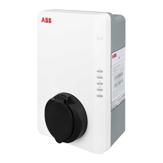
Page 17: Overview Of The Evse, Outside
Description 2.5.2 Overview of the EVSE, outside Connection for the EV Cabinet cover charge cable Enclosure Openings for the smart RFID reader meter connections Type plate Opening for the Ethernet cable Opening for the AC input cable LED indicators Part Function Connection for the To connect the EV charge cable... -
Page 18: Overview Of The Evse, Inside
Description 2.5.3 Overview of the EVSE, inside Socket for a Nano-SIM card Terminal block for the EV charge cable or the socket Part Function Maintenance cover To prevent access to the electrical components of the EVSE Ethernet connection To connect the ethernet cable Socket for a Nano-SIM card To connect the EVSE to the internet 3G/4G Smart meter connection To connect the cables for RS485 and ModBus... -
Page 19: Options
Description Options 2.6.1 Display EV charge cable, Type 2 2.6.2 2.6.3 Socket, Type 2 Socket The socket for an EV charge cable Type 2 is available with or without a shutter. BCM.V3Y01.0-EN | 001... -
Page 20: Ev Charge Cable, Type 1
The load management feature prevents that the system exceeds the grid capacity and prevents damage of the fuses. At times when the current demand is high, the Terra AC will limit the output of current. The current will rise again when there is availability on the grid. - Page 21 Description Error LED Internet connection LED E EVSE on/off LED Charging LED Cable and car detection, and car authorization LED Table 1: Error LED Status of the LED Status of the EVSE Error No error Table 2: Charging LED Status of the LED Status of the EVSE EV is fully charged or has stopped charging...
-
Page 22: Description Of The Mobile App For The Evse
Residual current error (DC There is residual current in the charge circuit. Current 6mA) leaks into the ground. (Not Applicable for North America, Model # Terra AC Wx-P8-xxxxx) Residual current error (AC There is residual current in the charge circuit. Current 30mA) leaks into the ground. -
Page 23: Safety
Safety Liability The manufacturer is not liable to the purchaser of the EVSE or to third parties for damages, losses, costs or expenses incurred by the purchaser or third parties if any target group mentioned in the related documents does not obey the rules below: •... -
Page 24: General Safety Instructions
Symbol Description Safety shoes Safety glasses General safety instructions • This document, the related documents and the warnings included do not replace your responsibility to use your common sense when you do work on the EVSE. • Only do the procedures that the related documents show and that you are qualified for. -
Page 25: Safety Instructions For Earthing
Safety instructions for earthing • This product must be connected to a grounded, metal, permanent wiring system, or an equipment-grounding conductor must be run with the circuit conductors and connected to the equipment grounding terminal or lead on the product. •... - Page 26 5. Do not use this product if the enclosure or the EV connector is broken, cracked, open, or shows any other indication of damage. 6. For AC power input wiring installation instruction, see Terra AC Installation Manual, section 7.3.2. 7. For AC power input terminal block connector screw torque requirements, see Terra AC Installation Manual, section 11.6.
-
Page 27: Installation
6. Do an inspection of the EVSE and the parts for installation for damage. 7. If you find damage or the parts are not according to the order, contact the local representative of the manufacturer (ABB EV Infrastructure). Site preparation Select the site 11.8... -
Page 28: Mechanical Installation
The site must be suitable to install the EVSE. Refer to section Procedure 1. Make sure that the space and the airflow around the EVSE are sufficient. Refer to 11.10.3 section 2. Make sure that the correct cables are available at the site. •... -
Page 29: Install The Evse On The Wall
Note: The mounting screws that are included in the delivery are serviceable for a brick wall. If you want to mount the EVSE on a different type of wall, contact your local representative of the manufacturer (ABB EV Infrastructure). Install the EVSE on the wall 1. -
Page 30: Electrical Installation
Electrical installation Electrical installation General electrical installation procedure Preliminary requirements • Procedure 1. Remove the maintenance cover. Refer to section 2. Install the AC input cable. • Insert the AC input cable. Refer to section • Connect the AC input cable. Refer to section 3. -
Page 31: Connect The Ac Input Cable
Refer to section 5. Tighten the screws (A) to the correct torque. 11.16 For the specification, refer to section 7.3.2 Connect the AC input cable for North America, Model # Terra AC Wx-P8-xxxxx Preliminary requirements • • Torque screw driver... -
Page 32: Secure The Cables
Electrical installation • • Torque screw driver AC input cable (3 phase, TN, TT networks) Procedure 1. Loosen the screws (A). 2. Insert the cable connector into the terminal block (B). 3. Connect these wires: 1. Earthing wire (C) 2. Neutral wire (D) 3. -
Page 33: Connect The Ethernet Cable
Electrical installation 1. Remove the membrane (A) from the EVSE. 2. Make a hole in the center of the membrane. 3. Install the membrane. 4. Put the Ethernet cable (B) through the cable inlet hole. 7.4.2 Connect the Ethernet cable Preliminary requirements The Ethernet cable is inserted. -
Page 34: Connect The Wires For The Smart Meter Communication
Electrical installation 7.4.4 Connect the wires for the smart meter communication Connect the smart meter with ModBus RTU over RS485 to the EVSE. Preliminary requirements • • Slotted screw driver Smart meter with ModBus RTU interface • Wire for RS485. Refer to 11.13.4 section . -
Page 35: Replace The Ev Charge Cable
Electrical installation Replace the EV charge cable Preliminary requirements • EV charge cable might be EV charge cable within the determined to be defective specifications. Refer (refer to Troubleshooting 11.13 section section or customer service). The replacement of the EV charge cable must be done by an official electrician •... - Page 36 Electrical installation Procedure (North America, Model # Terra AC Wx-P8-xxxxx) 7. Get access to the EV charge cable connection: a. Remove the cabinet cover. Refer to section b. Remove the maintenance cover. Refer to section c. Remove the plastic cover.
-
Page 37: Commissioning
Commissioning This commissioning is only applicable for single Terra AC use case scenario by using Chargersync APP. For other scenarios (Chargersync Web Portal, OCPP) please contact sales support. General commissioning procedure 1. Energize the EVSE. Refer to section 2. Set up the EVSE. Refer to section 3. -
Page 38: Connect The Evse With The Mobile App
Connect the EVSE with the mobile app Preliminary requirements • Mobile device with the mobile app Procedure 1. Find your pin code in the package with the RFID card. • The pin code has 8 characters. • The letters are case-sensitive. 2. -
Page 39: Access To Parts
Access to parts Remove the cabinet cover 1. Remove these parts: • Screws (A) • Cabinet cover (B) Install the cabinet cover 1. Install these parts: • Cabinet cover (A) • Screws (B) BCM.V3Y01.0-EN | 001... -
Page 40: Remove The Maintenance Cover
Remove the maintenance cover 1. Remove these parts: • Screws (A) • Maintenance cover (B) Install the maintenance cover 1. Install these parts: • Maintenance cover (A) • Screws (B) BCM.V3Y01.0-EN | 001... -
Page 41: Troubleshooting
Troubleshooting 10.1 Troubleshooting procedure 1. Try to find a solution for the problem with the aid of the information in this document. 2. If you cannot find a solution for the problem, contact your local representative of the 1.12 manufacturer. Refer to section 10.2 Troubleshooting table Problem... - Page 42 Problem Possible cause Possible solution There is a relay con- The relay contact is over- 1. Examine the relay contact. tact failure heated or defective. 2. If necessary, adjust the current. 3. If necessary, replace the relay contact. Cable Mismatch The rated current capacity Connect a cable that has the same rated current as the EVSE.
-
Page 43: Energize The Evse
Problem Possible cause Possible solution The EV charge cable is not 1. Examine the connection of the connected correctly. EV charge cable. 2. If necessary, connect the EV charge cable. There is a problem with the Make sure that you have mobile app or the RFID registered in the mobile app. -
Page 44: Technical Data
EVSE Type The EVSE type is a code. The code is has 10 parts: A1 - A10. Code part Description Value Meaning of the value Brand name Terra AC Type Wallbox Column Power output 3.7 kW 7 kW 9 kW... -
Page 45: Mass
11.2 Mass EVSE type Weight [kg] Terra AC wallbox type 2 with socket (Europe) Terra AC wallbox type 2 with an EV charge cable (Europe) Terra AC wallbox type 1 (North America) 11.3 Protective device compliance 11.3.1 Protective device compliance (Europe) -
Page 46: Parts Included In The Delivery
Minimum Type A, with a rated residual operation current of maximum 30 mA Note: Internal to EVSE is DC fault current monitoring > 6mA 11.3.2Protective device compliance (North America, Model # Terra AC Wx-P8-xxxxx) Requirements Specifications Dedicated upstream protection device(s) -
Page 47: General Specifications
Technical data 11.5 General specifications Parameter Specification Compliance and safety • IEC/EN 61851-1 • IEC/EN 62311 • IEC/UL 62479 • IEC/UL 62955 TüV listed conforming to UL 2594, UL 2231-1, UL 2231-2, UL 1998 • CSA C22.2. NO.280 Certification CE, MID, TüV, Energy Star IP or NEMA rating The type plate shows the specification. -
Page 48: Required Tools For Installation
Required tools for installation 11.6 Parameter Specifications Hammer Spirit level Drill Torque screw driver, cross Torque screw driver, slotted For terminal blocks and plugs with 5 mm pitch Ambient conditions 11.7 Parameter Value Operation temperature -30° C to +50° C -30°... -
Page 49: Noise Level
Technical data 11.9 Noise level Parameter Specification Noise level Maximum 35 dB(A) 11.10 Dimensions 11.10.1 AC input with socket, cable Type 2 Width of the EVSE Height of the EVSE Depth of the EVSE Distance from the bottom of the EVSE to the center of the socket. -
Page 50: Ac Input With Ev Charge Cable
11.10.2 AC input with EV charge cable Width of the Height of the EVSE EVSE Y Depth of the EVSE Parameter Value [mm] 11.10.3 Space requirements for installation EVSE BCM.V3Y01.0-EN | 001... -
Page 51: Ac Input Specifications
Parameter Specification [mm] Specification [inches] Technical data > 200 > 8 11.11 Z2 (indoor use) 450 to 1200 18 to 48 11.11.1 Z2 (outdoor use) 600 to 1200 24 to 48 AC input specifications General specifications Parameter Specification Earthing systems TN-S TN-C-S Frequency... -
Page 52: 230 Vac 1-Phase (Europe)
11.11.3 230 VAC 1-phase (Europe) 230 VAC, maximum 264 VAC 11.11.4 240 VAC (for North America, Model # Terra AC Wx-P8-xxxxx) U1 240 VAC, maximum 264 VAC 11.11.5 AC input specifications (Europe) Parameter Specification Input AC power connection 1 phase or 3 phase... -
Page 53: Ac Input Specifications (North America)
Technical data 11.11.6 AC input specifications (North America) Parameter Specification Input AC power connection 240 V AC Standby power consumption 3.6 W Earth (ground) fault protection internal 20 mA AC CCID 11.12 General logic interface specifications Specification Parameter Connectivity Mobile communication with Nano-SIM socket •... -
Page 54: Ac Input Cable (North America)
Cable shielding (optional) The local rules require shielded cables. The cable shielding must be connected to the PE rail at the two ends of the cable. Diameter of the phase conductors Refer to the local rules. Diameter of the PE conductor The same as the diameter of the phase conductors •... -
Page 55: Dry Contacts Input
Technical data Parameter Specification Connector type for the EV charging station Terminal block plug and screws Conductor type Twisted pair, shielded cable (recommended) Conductor size for the terminal block plug Europe (IEC) cross-sectional area: 2.5 (allowed) to 0.5 mm North America (UL): 12 AWG to 30 AWG Conductor size for the terminal block plug Minimum 24 AWG (0.5 mm (recommended) -
Page 56: Ev Charge Cable Specifications
The wire AWG and cross section are based on a copper wire type. 11.13.7 EV charge cable specifications Parameter Value [m] Length 5 (for Europe models) (for North America, Model # Terra AC Wx-P8- xxxxx) 11.14 AC output specifications AC output specifications (Europe) 11.14.1 Parameter... -
Page 57: Specific Power Consumption Specifications
Technical data AC output voltage range 110 - 240V AC (1 phase) Connection standard Type 1 cable according to SAE J1772 11.15 Specific power consumption specifications Specification [W] Power consumption during normal operation Charging Mode 1 Phase Charging Mode 3 Phase Torque specifications 11.16 Parameter... -
Page 58: Display Instructions
Display Instructions Scope This document clarifies the display layout of Terra AC wallbox in JUNO project, which is for compliance of MID and all values on this screen will be strictly qualified for measurements verified requirements of MID. BCM.V3Y01.0-EN | 001... - Page 59 Technical data Introduction Booting This screen shows the brand information as a loading page when the charger is booting. Standby/Idle This screen shows when the charger is in an idle status which means the charger is available for charging. Position of title Date Guide Total Energy Delivered...
- Page 60 Authorization Case 1. This screen shows when the connector plugged in but the charging is not authorized. Case 2. This screen shows when the charging is authorized but the connector is not plug in. BCM.V3Y01.0-EN | 001...
- Page 61 Technical data Charging preparing This screen will be displayed when the charger is preparing to charge, which means the charging process is initializing. BCM.V3Y01.0-EN | 001...
- Page 62 Charging Case1 .This screen will be displayed when a single-phase charger is charging. Real-time voltage and current Real-time power Energy delivered and duration of this charging process Multi-phase Current and voltage will alternate display phases. Real-time voltage and current per phase.
- Page 63 Technical data Charging completed Start Time Energy delivered and duration of this charging process. BCM.V3Y01.0-EN | 001...
- Page 64 Fault detected Faults will be displayed respectively according to the different types. BCM.V3Y01.0-EN | 001...
Need help?
Do you have a question about the Terra AC and is the answer not in the manual?
Questions and answers