Fermax BUS2 Technical Manual
Hide thumbs
Also See for BUS2:
- Manual (40 pages) ,
- Installer manual (28 pages) ,
- Quick start manual (12 pages)
Table of Contents
Advertisement
Quick Links
Advertisement
Table of Contents

Related Manuals for Fermax BUS2


Summary of Contents for Fermax BUS2
- Page 1 TECHNICAL MANUAL BUS2 SYSTEM Section I BUS2 System Description...
- Page 2 Code 97462I-1 V07_09 This technical document of an informative nature is published by FERMAX ELECTRONICA S.A.E., which reserves the right to modify the technical characteristics of the products referred to herein at any time and without prior notice. These changes will be reflected in subsequent editions of this document.
-
Page 3: Table Of Contents
SECTION I - DESCRIPTION OF BUS2 SYSTEM BUS2 SYSTEM ................................5 - General Characteristics ............................5 - Basic diagram for BUS2 video door entry system ....................6 - Operating principle of BUS2 system ........................7 - Installation and start-up instructions for BUS2 systems ..................9 BUS2 PANELS. - Page 4 B B B B B US2 B B B B B US2 Page 4 Code 97462I-1 V07_09...
-
Page 5: Bus2 System
The BUS2 system can manage buildings with up to 199 apartments. * One or two door or video door access points (entrances) The BUS2 system enables up to two access points to be installed in the same building, with the possibility of combining audio and video entry devices. -
Page 6: Basic Diagram For Bus2 Video Door Entry System
B B B B B US2 B B B B B US2 Basic diagram for BUS2 video door entry system Page 6 Code 97462I-1 V07_09... -
Page 7: Operating Principle Of Bus2 System
B B B B B US2 Operating principle of BUS2 system The BUS2 door entry/video door entry system functions like a large, single-line kit. The call executed from the outdoor entry panel is directed via the 2-wire bus through the branch and floor distributors to the desired terminal, creating a single path without any further branching. - Page 8 The BUS2 relays have two modes of operation: - Individual: the BUS2 relay is programmed with an address (in the same way as the apartment terminals), which in this case must coincide with the terminal address from which the relay will be activated by pressing the F1 or F2 button (upon pressing F1 or F2, the terminal will send the activation command via the bus to the relay programmed with the same address).
-
Page 9: Installation And Start-Up Instructions For Bus2 Systems
If two outdoor entry panels exist, one of them must be configured as the main panel and the other as secondary panel in order to differentiate between them. The panels have a configuration bridge for this (see section ‘BUS2 Panels’). -
Page 10: Bus2 Panels
BUS2 PANELS Two possibilities: - BUS2 panels: panels with BUS2 amplifier, pertaining to the BUS2 system. These are connected directly to the bus using 2 wires without polarity using the terminals (B, B) in the BUS2 amplifier. The BUS2 audio and video (colour) panels are available in the following designs and formats: - Designs: new panel Cityline (continuous profile) and Citymax (modular). -
Page 11: Bus2 Panels With "Bus2 Amplifier
The BUS2 amplifier is fitted with a potential-free relay which enables continuous (12Vdc, 0.5A) or alternating (12Vac, max 4A) lock-release connection. * Without cabling errors The BUS2 system has been designed to prevent cabling errors, given that the connection is carried out using 2 polarity-free wires. * Restore default values The BUS2 amplifier has a ‘Reset’... -
Page 12: Bus2 Amplifier
B B B B B US2 B B B B B US2 BUS2 amplifiers The BUS2 amplifier is a common element of all BUS2 panels and manages all BUS2 system functions: call, two-way communication, door opening, programming..It is available in audio and video (colour). - Page 13 Maximum audio power in direction street -apartment 0.15 W * Restore default values Reset The BUS2 amplifier has a ‘Reset’ function which can be used to restore programmed default parameters (door and hall lock-release time, access codes, mapping). - Reset from button panels To restore the default values, follow the steps below: 1.- Reset amplifier: disconnect power supply...
-
Page 14: City Bus2 Continuous Profile Panels
* CITY BUS2 panel typology Aesthetically, the CITY BUS2 panels are classified in 9 series, all of which have the same width, but different heights. The new range of CITY panels enables installation on the same audio or video amplifier range thanks to the fact that the remote camera is built into the video amplifier module. -
Page 15: Call Extension Module
* Call extension module, ref. 2441 One of the advantages offered by the BUS2 system is that no call wires are used. This is possible because the call is made through the transmission of a digital code generated by the amplifier in the outdoor entry panel when a specific call button is pressed. -
Page 16: City Bus2 Modular Panels
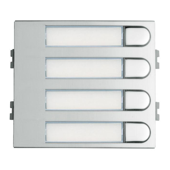
The button modules are available with 2, 4 and 8 buttons. Calls to apartments are made by pressing the corresponding call button assigned to the apartment. - Display module and Direct keypad: Enable the compilation of Direct panels and Digital BUS2 modules. -
Page 17: Button Module Interconnection
As mentioned above, the modular panels do not require a call extension module, given that the button modules generate the BUS2 call code corresponding to each apartment (do not confuse the BUS call code or BUS call address with the apartment door no.). -
Page 18: Direct Bus2 Panels
- Programming the door lock-release time between 1 and 99 seconds. * DIRECT BUS2 panel typology The size of the DIRECT BUS2 panels is always the same, series 4 (with 1 recess: series 6), regardless of the number of apartments. - Page 19 Programming the door lock-release code on Direct BUS2 panels All Direct BUS2 panel models enable the door to be opened from the outdoor entry panel by entering a 4-digit code. Below, the steps to be followed to activate and configure the door lock release using a code are shown: * Door lock-release activation sequence.
-
Page 20: Digital Bus2 Panels
This Directory Panel is optional as its function is already provided by the LCD display. The directory panel is fitted with a set of lamps which must be connected to the BUS2 amplifier (see internal panel cabling diagrams). - Page 21 Telephone code search is carried out on the screen and %’ is pressed. Like the rest of the BUS2 system, the line number must be a value between 001 and 199 and it must have been programmed previously in the Door opening code telephone/monitor.
-
Page 22: Panels With "4+N Amplifier And Bus2 Adapter
BUS2 system enormous flexibility and service range. In addition to this, it is possible to add an ‘ADS keypad’ and ‘BUS2 display’ to the ‘4+N / BUS2 adapter’ equipment, thus significantly expanding the system’s range of services. This is done using the keypad and display functions: keypad access control, electronic directory, etc. -
Page 23: Bus2 Adapter
B B B B B US2 BUS2 adapter 1 CN3. Connector test: Enables the ‘BUS2 verifier’ to be connected to check the system status or to programme the apartment terminals. CN2: Call extension module connection (button panels), keypad (direct panels) or display (digital panels). -
Page 24: Bus2 System Reception
The Decoder MDS/BUS2 requires simple programming (see section ‘Decoder MDS/BUS2 Programming’). If, in addition to the reception, the BUS2 system features a BUS2 panel, the ‘BUS2 switcher, ref. 3246’ must be installed alongside the Decoder MDS/BUS2. This switcher enables the selection of and communication between the active panel/reception and the general bus, thus isolating other panels/reception or equipment which may be connected to the bus (see section ‘Basic Devices of BUS2 systems - BUS2 switcher’). - Page 25 B B B B B US2 B B B B B US2 Description of reception controls Display Offers a range of information when using the Central Reception. Search keys Press the arrows to locate the name of the resident you wish to call. Start the search by pressing the right arrow.
- Page 26 B B B B B US2 B B B B B US2 Operating Modes The characteristics of the different operating modes for buildings with one sole Central Reception are: DAY MODE * The Central Reception can make and receive calls from the telephones or the intercommunication panels (using panel decoders).
-
Page 27: Mds/Bus2 Decoder
The ‘MDS/BUS2 decoder’ acts as an interface between the BUS2 system and the MDS system, enabling the connection between the MDS reception and MDS panels in BUS2 systems, whilst extending the range of services offered by the BUS2 system: locked entrances with multiple general MDS access points, central receptions, etc. - Page 28 Telephone 4: FFFF 8. Exit programming Note: The combination of MDS/BUS2 systems enables the creation of systems with multiple BUS2 interior blocks and MDS general entrance (various panels or reception). In this type of system, the allocation of initial and final addresses differs from the process described here. For more information on the combination of MDS and BUS2 systems, please consult the ‘MDS/BUS2 Technical Manual’.
-
Page 29: Bus2 System Basic Devices
B B B B B US2 BUS2 SYSTEM BASIC DEVICES In addition to the outdoor entry panels and receptions, the BUS2 systems require a set of devices to route and establish communication between the panel/reception and the apartment terminals. Below, the function of each basic device within the BUS2 system is described and explained. -
Page 30: Bus2 Switcher
B B B B B US2 BUS2 switcher (Ref.3246) In BUS2 systems with more than 1 access (two door entry/video door entry access points or a combination of these), a ‘BUS2 switcher ref.3246’ is required. The BUS2 panel switcher is a device which connects the active panel with the general bus, isolating other panels or equipment which could be connected to the bus. -
Page 31: Bus2 Branch Shunt
The ‘branch shunt’ separates the BUS2 signal into various trunks (branches). The BUS2 branch shunt is a device responsible for connecting the entry panel with the branch on which the active terminal (monitor or telephone) is located, isolating the rest of the branches or systems. This shunt enables the communication of data from the remaining inactive terminals, meaning that they can communicate with the rest of the system on a data basis. -
Page 32: Bus2 Distributors
(monitors/telephones). The BUS2 distributor is a device which is responsible for routing the bus from the panel to the active apartment terminal (monitor/telephone), maintaining the power supply and the data signal on all monitors at all times. The distributor opens the path to the active terminal (establishing point to point contact between the panel and the active terminal) and prevents audio and video signals from reaching the rest of the branches. - Page 33 Distribution output on Distribution output active, all standby. Only transmits signals transmitted (audio, power supply data and video, data and power supply). Entrance * Basic BUS2 distributor connection diagrams TERM NO TERM NO TERM Code 97462I-1 V07_09 Page 33...
-
Page 34: Bus2 Relay
Led Relay ON: Relay indicator LED in programming mode. BUS2 addresses can be programmed on the BUS2 relay (from 1 to 199) so that they will only respond to activation commands from a device whose address corresponds to one of those programmed at an earlier position on the relay. - Page 35 B B B B B US2 B B B B B US2 * Basic BUS2 distributor connection diagrams Install the BUS2 relay at an intermediate point on the bus. Do not install it at the end of the backbone. BUS2 relay 10xsec...
- Page 36 (1) The BUS2 relay is activated if the command generated by a device agrees with that configured on the BUS2 relay. The BUS2 relay can be configured to respond to commands from all the devices or just from certain ones. This operating mode is configured via the DSW1.
- Page 37 DWS2). This activation is additional to the activation of the BUS2 relay. In ‘call from panel’ mode, when a call is made from the entry panel, in addition to activating the BUS2 relay, the relay on the panel from which the call was made is activated (the timing of the panel amplifier relay depends on the time programmed on the panel itself).
-
Page 38: Bus2 Repeater
B B B B B US2 BUS2 repeater (Ref.3249). Signal regenerator The ‘BUS2 Repeater’ amplifies the BUS2 signal and as a result increases the distance covered by the system and the number of terminals (up to a maximum of 199 terminals). -
Page 39: Bus2 System Power Supplies
BUS2 door entry/video door entry systems. The BUS2 systems are supplied with 24 Vdc, although depending on the system (number of monitors/telephones installed, type of door lock-release used, distance, etc.) the necessary power supply may vary in model and number: - Source Ref. - Page 40 B B B B B US2 B B B B B US2 * Basic BUS2 distributor connection diagrams Source connection ref. 4843 with adapter ref. 3243 Source connection ref. 482x [B B][B B] Additional source Additional source connection ref. 4840 Additional source connection ref.
-
Page 41: Lock Releases: Continuous And Alternating Lock Release Connection
B B B B B US2 Electric door lock-release The BUS2 amplifiers have a potential-free relay (C, No, Nc) which enables the use of both continuous and alternating door lock-release mechanisms. The 12 Vdc door lock-release supply can be carried out through the BUS2 amplifier (up to a maximum door lock-release consumption of 0.4A). -
Page 42: Apartment Terminals
The apartment terminals enable the user to establish audio/video communication with the outdoor entry panel, open the door, call the reception, etc. Like the rest of the BUS2 devices, the apartment terminals are connected to the system via 2 wires without polarity (B,B). -
Page 43: Video Terminals: Bus2 Monitors
(where one exists), hold the button down for 2 seconds. Buttons for additional functions. Enables activation of relays (BUS2 or conventional) to use additional devices: secondary door opening, additional lighting activation, etc. Code 97462I-1 V07_09... -
Page 44: Connectors And Connections
B B B B B US2 Connectors and connections The BUS2 apartment terminals (monitors/telephones) are fitted with connectors which are installed in the apartment to connect the apartment terminal to the system. Depending on the apartment terminal model, the connector format will vary, not the main connection terminals (Bin, Bout, F1, F2, CT, T,...), so that the cabling for the various terminals is carried out following the same connection diagram. - Page 45 B B B B B US2 B B B B B US2 * Basic BUS2 distributor connection diagrams Distribution system Cascade system Detail of LOFT monitor connection to connector Connector Connector base Code 97462I-1 V07_09 Page 45...
-
Page 46: Terminal Programming (Bus2 Monitors And Telephones)
B B B B B US2 BUS2 terminal programming (monitors and telephones) The programming procedure for BUS2 terminals is the same for monitors and telephones. The apartment terminals will not function if they have not been programmed BUS2 terminal programming is carried out in 2 steps: 1.- Terminal programming setup:... -
Page 47: Bus2 System Verifier
B B B B B US2 SYSTEM VERIFIER BUS2 (Ref.3252) The BUS2 system verifier is a device aimed at technical services and installers, which allows verification of the status of a BUS 2 system using the following functions: • Aut: Automatic system verification. Automatic address range test (call codes assigned to apartment terminals. - Page 48 MOD causes the verifier to switch off. Automatic mode (AUT) In automatic mode ‘AUT’, the data status of the telephone/monitors in the BUS2 system is verified. To this end, the verifier sends a test command to the range of telephone/monitor addresses selected and awaits a response from each address.
- Page 49 B B B B B US2 Spy mode (SPY) In SPY mode, the verifier receives any data circulating through the BUS2 or any user commands ( making a call, opening a door, etc) and shows it on the display in the following manner: •...
-
Page 50: Advanced Programming
Involves a method inverse to the current process. The steps to be followed are detailed below: 1. Programme the monitor locally and autonomously using the BUS2 system verifier or from an outdoor entry panel or reception with keypad. (The iLOFT and Compact monitors allow programming via the monitor itself). -
Page 51: Lock-Release Times On Button Panels
B B B B B US2 B B B B B US2 ADVANCED PROGRAMMING: Door lock-release times on button panels There are two programmable lock-release activation times: - Lock-release time set from the residence. - Lock-release time set from the exit button (connected to the ‘BS’ and ‘-’ terminals). To programme the activation time follow the steps below: 1.- With the power supply disconnected, execute a short circuit between the terminals ‘Bs’...
Need help?
Do you have a question about the BUS2 and is the answer not in the manual?
Questions and answers