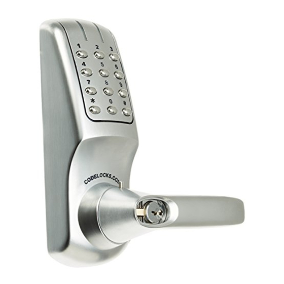
CodeLock CL5000 Installation Instructions Manual
Hide thumbs
Also See for CL5000:
- Installation instructions manual (13 pages) ,
- Programming & operating instructions (4 pages)

Related Manuals for CodeLock CL5000


Summary of Contents for CodeLock CL5000
- Page 1 Installation Instructions CL5OOO CL5010 Mortice Latch CL5010 Back to Back CL5010 Panic Access Kit CL5020 Mortice Lock...
- Page 2 CONTENTS Check the contents of the box are correct according to the model. This box should also contain an Installation Template and Programming and Operating Instructions. Box Contents 5010 5010BB 5020 1 Front Plate 2 Back Plate 3 Back to Back Fixing Plates 4 Lever Handles 5 Gaskets (x2) 6 Sprung Spindle...
- Page 3 DIMENSIONS OPERATIONS CHECK SPECIAL FIXING NOTE REMOTE RELEASE OPTION CL5010, CL5010BB LATCH FUNCTION CL5020 ANTI-PANIC LOCK FUNCTION You should familiarise yourself with the operation of the lock and check that all parts work properly. Cables are provided for the REM 1 and REM 2 terminals on the Outside handle turns freely without operating the latchbolt.
- Page 4 CL5010 INSTALLATION INSTALLATION OF LOCKS Lightly mark a height line on the edge and both faces of the door and on the door Screw the cable tube into the front plate, passing the cable Check that the spindle turns freely, and the latch retracts and jamb, to indicate the top of the lock when fitted.
- Page 5 The Blue LED will flash and the handle will thickness and engagement with both the Codelock and panic when the door is closed, even when it is slammed shut. now retract the latch. Each unit is standalone and will need to be device.
- Page 6 CL5020 ANTI-PANIC MORTICE LOCK INSTALLATION IMPORTANT: The Anti-Panic Mortice Lock has features which Lightly mark a height line on the Check that the 2 screws have been removed from the follower on Position the front plate over the spindle passing the cable through are not found in most other locks and so it is recommended edge and both faces of the door, and the outside of the door.
- Page 7 Freephone: 0800 393 405 CODELOCKS INC US Tel: +1 714 979 2900 Fax: +1 714 979 2902 sales@codelocks.us www.codelocks.us Helpline, service & spares Toll free: 1.877.codelock CODELOCKS (Australia) PTY LTD Tel: +61 2 9882 1009 Fax: +61 2 9882 6030 sales@codelocks.com.au www.codelocks.com.au ...
Need help?
Do you have a question about the CL5000 and is the answer not in the manual?
Questions and answers