Advertisement
ASKOWALL
‐OP
Fitting instruction, user manual and service
Please keep in a safe place
Wall console ready for connec on for hea ng water
ASKOWALL
‐OP
012‐5500
Index
General safety informa on
Design
Func onal descrip on
Scope of delivery
Assembly and installa on
Filling
Leakage check
Se ng of thermosta c valve
Overview electrical connec on
Closing of insula on cover
Installa on instruc ons
Electrical connec on
Electric diagram for 012‐5500
ASKOWALL
‐OP
MVGASV_012‐5500_01_en
www.askoma.com
Page 2
Page 3
Page 4
Page 4
Page 5
Page 9
Page 10
Page 10
Page 11
Page 12
Page 14
Page 13
Page 1
Advertisement
Table of Contents

Related Manuals for ASKOMA ASKOWALL-OP


Summary of Contents for ASKOMA ASKOWALL-OP
- Page 1 Installa on instruc ons Page 14 Electrical connec on Electric diagram for 012‐5500 Page 13 ASKOWALL MVGASV_012‐5500_01_en www.askoma.com Page 1 ‐OP...
-
Page 2: General Safety Information
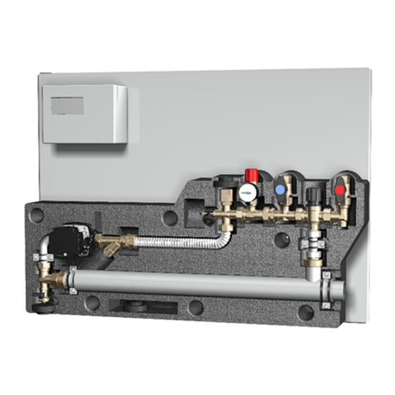
ASKOWALL MVGASV_012‐5500_01_en www.askoma.com Page 2 ‐OP... - Page 3 Vent valve 4. Connec on for possible expansion tank (1" internal thread, flat sealing) 5. Pressure relief valve 6. Return flow shutoff & OXYban hose connec on 7. Flow shutoff & OXYban hose connec on 8. Thermosta c valve 50 ‐ 75°C 9. 1½" threaded connec on for screw‐in heater 10. Drain cock 11. Circula on pump 12. Insula on housing 13. Instantaneous water heater ASKOFLOW 14. Console rear wall 15. Electrical junc on box for pump incl. OFF‐delay relay ASKOWALL MVGASV_012‐5500_01_en www.askoma.com Page 3 ‐OP...
-
Page 4: Functional Description
S c o p e o f d e l i v e r y The delivery includes the ASKOWALL incl. the rear wall and two‐part insula ng sleeve, these as‐ ‐OP sembly instruc ons, four screws (6 x 70mm), four dowels (8 x 50mm) and a piece of hose for the connec on to the blow‐off line. cle 012‐5500 ASKOWALL also includes a housing for connec ng the pump. ‐OP The ASKOWALL does not include any connec on hoses or screw‐in heater. This screw‐in heater is ‐OP required for commissioning, but must be ordered separately. ASKOWALL MVGASV_012‐5500_01_en www.askoma.com Page 4 ‐OP... -
Page 5: Assembly And Installation
ASKOWALL ‐OP Assembly and installation Material and tools Various open‐end wrenches, impermeable material, a Ø 8mm rock drill & impact drill (for wall moun ng on a brick or concrete wall), a hea ng vent key and hoses for filling and ven la on are requi‐ red for the installa on of the ASKOWALL . ‐OP If the ASKOWALL is connected to a heat exchanger, a suitable expansion vessel is necessary. ‐OP ASKOWALL MVGASV_012‐5500_01_en www.askoma.com Page 5 ‐OP... - Page 6 ASKOWALL ‐OP Assembly and installation 6 7 6 Opening the insula on cover Before opening the insula on cover, the two shut‐off valves of flow and return (no. 6 and no. 7) must be closed. Remove the insula on cover carefully and, if possible, evenly so that the six locking pins on the cover do not tear off. Re ghten screw connec ons All screw connec ons marked with a red dot must be re ghtened for safety reasons. A leak test has already been carried out at the factory during manufacture. ASKOWALL MVGASV_012‐5500_01_en www.askoma.com Page 6 ‐OP...
- Page 7 ASKOWALL ‐OP Assembly and installation ASKOWALL can be a ached to the wall using the four screws supplied. ‐OP The holes have to be drilled according to the drawing. ASKOWALL MVGASV_012‐5500_01_en www.askoma.com Page 7 ‐OP...
- Page 8 ASKOWALL ‐OP Assembly and installation 6 6 6 7 Seal the screw‐in heater with approved sealing material and screw it in The screw‐in heater‘s cable glands must be posi oned downwards Connect the drain hose of the safety valve to the on‐site drain according to the regula ons Connect the supply and return lines on the shut‐off valves (no. 6 and no. 7) of the ASKOWALL . ‐OP Therefor the connec on hoses for ASKOWALL with the ar cle number 012‐0130 can op onally ‐OP be used ASKOWALL MVGASV_012‐5500_01_en www.askoma.com Page 8 ‐OP...
- Page 9 ASKOWALL ‐OP Return flow shutoff (no. 6) and flow shutoff (no. 7) must be closed. Connect the flow line (right / red) to the top of the storage tank. Connect the return line (le / blue) to the bo om of the storage tank. Connect the on‐site mobile ven la on hose to the ven la on valve (no. 3) and open it. Connect the hea ng water inlet to the drain cock (no. 10) and open the drain cock. The ASKOWALL is filled by supplying the hea ng water, the air can escape from the open vent ‐OP valve. If only hea ng water comes out of the vent valve, the ASKOWALL is completely filled and the ‐OP vent valve (no. 3) can be closed. The drain cock must be closed before dismantling the hea ng water supply. ASKOWALL MVGASV_012‐5500_01_en www.askoma.com Page 9 ‐OP...
-
Page 10: Leakage Check
If a screw connec on is leaking, it must be re ghtened. Setting of the thermostatic valve Se ng the output temperature to the buffer tank (opening temperature of the thermosta c valve) 1. Pull the lower plas c ring up and hold it there. 2. Set the rotary control to the desired temperature (turn). Then release the lower plas c ring and snap it into place. ASKOWALL MVGASV_012‐5500_01_en www.askoma.com Page 10 ‐OP... -
Page 11: Electrical Connection
A connec on line must be created between the Fronius Ohmpilot and the connec on housing. This is used to control the pump in the ASKOWALL . ‐OP A supply line for the load circuit of the hea ng element must be created. The power consump ‐ on and the connec on op ons are device‐dependent (see separate installa on / opera ng in‐ struc ons for the screw‐in heater) ASKOWALL MVGASV_012‐5500_01_en www.askoma.com Page 11 ‐OP... - Page 12 ATTENTION: Before closing the insula on cover, the two shut‐off valves of flow and return (no. 6 and no. 7) must be closed. Otherwise the insula on cover cannot be closed. 1. Close the shut‐off valves of flow and return (no. 6 and no. 7). 2. The two insula on washers supplied are for closing the connec ons of the expansion tank (no. 4) and the drain cock (no. 10) that may not be used. These can be inserted into the prefabricated slots. 3. A er closing the cover, the shut‐off valves of flow and return can be opened again. ATTENTION: Pipes, fi ngs and connec on hoses can be hot, there is a risk of burns! ASKOWALL MVGASV_012‐5500_01_en www.askoma.com Page 12 ‐OP...
-
Page 13: Electric Diagram
ASKOWALL ‐OP Electric diagram Electric diagram for 012‐5500 ASKOWALL ‐OP ASKOWALL MVGASV_012‐5500_01_en www.askoma.com Page 13 ‐OP... -
Page 14: Installation Instructions
I n t h e e v e n t o f t h e f o l l o w i n g t h e g u a r a n t e e i s v o i d : ‐ Not complying with this paperwork „Fi ng instruc ons, user manual, and service“ ‐ Not complying with the storage heater manufacturer‘s fi ng instruc ons ‐ Technical modifica ons, repairs or tampering with the device (including exchanging the pump, piping or the valve) ‐ Hea ng up drinking water ‐ Applica ons for which the device was not designed ‐ Installa on of a foreign hea ng element ‐ Incorrect opera on and maintenance ‐ Not complying with direc ve VDI 2035 All power supply circuits must have been switched off before ATTENTION! accessing the connection terminals. ASKOWALL MVGASV_012‐5500_01_en www.askoma.com Page 14 ‐OP...
Need help?
Do you have a question about the ASKOWALL-OP and is the answer not in the manual?
Questions and answers